
Installation Instructions

Document No. 540-1028
Installation Instructions
October 26, 2016
Page 4 of 5 Siemens Industry, Inc.
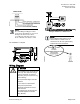
NOTE:
When wiring any actuator that uses a 0 to
10V control signal and ties AC neutral to DC
common, an additional wire
must connect
the actuator AC neutral to the DC common
of the PTEC/TEC AO being used to control
the actuator.
24 Vac Modulating Control.
Actuator
Symbol
TEC
Connection
Function
Terminal
Connection
Standard
Color
1
H
Supply (SP)
G
Red
2
C
Neutral (SN)
G0
Black
8
AO3 – 15
(+)
0 to 10V
input signal
Y
Gray
--
C to AO3
16 (-)
Common
jumper
--
--
*A voltage/current switch for AI 3 is located under the
controller’s cover on the circuit board (behind AI 3). It must
be set either to voltage or current position according to
function.
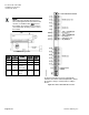
Application 2497 – Extended I/O Controller.