Desigo™ Touch Panel Clients Commissioning A6V11604303_en--_b 2020-04-30 Smart Infrastructure
Edition notice Edition notice Technical specifications and availability subject to change without notice. This document may not be reproduced, disseminated to third parties or processed and its contents may not be used or disclosed without express permission. Non-compliance shall result in compensation for damages. All rights, including those resulting from a successful patent application and registration of a utility model or design patent, are reserved.
Copyright Copyright This document may be duplicated and distributed only with the express permission of Siemens, and may be passed only to authorized persons or companies with the required technical knowledge.
Trademarks Trademarks The trademarks used in this document are listed together with their legal owners in this section. The use of these trademarks is subject to international and national statutory provisions. Desigo ® is a registered trademark of Siemens Schweiz AG. Chrome and the Chrome logo are trademarks of Google LLC. Firefox is a registered trademark of Mozilla Foundation. Internet Explorer is a trademark of Microsoft Corporation.
Table of Contents 1 Safety notes ............................................................................................................................................ 8 2 About this document ............................................................................................................................. 12 2.1 Scope .......................................................................................................................................................... 12 2.
| 40 A6V11604303_en--_b
Cybersecurity disclaimer Cybersecurity disclaimer Siemens provides a portfolio of products, solutions, systems and services that includes security functions that support the secure operation of plants, systems, machines and networks. In the field of Building Technologies, this includes building automation and control, fire safety, security management as well as physical security systems.
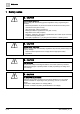
1 Safety notes 1 Safety notes CAUTION General safety regulations Please comply with the following general regulations during engineering and execution: ● ● ● ● ● ● Measures/prohibitions to prevent the hazard of electrical and mains power ordinances for the given country. Other applicable, national regulations. Building installation regulations for the given country. Regulations of the utility company.
Safety notes 1 CAUTION NEC (North America) Use of class 2 transformers limited to 100 VA or class 2 circuits at max. 100 VA by a non-limited transformer of max. 400 VA, combined with overcurrent protection (T 4 A fused) for each AC 24 V device. Multiple fuses for multiple insulated secondary circuits per transformer are possible (see Power requirements). The same applies to DC 24 V power supplies.
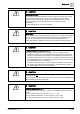
1 Safety notes CAUTION Transformer specification AC 24 V IEC: Use safety insulating transformers as per IEC 61558 with double insulation designed for 100% duty to supply SELV or PELV circuits. USA: Class 2 circuits per UL 5085-3 Power taken from the transformer should be at least 50% of nominal load for efficiency reasons (effectiveness). Transformer nominal power should be at least 25 VA. For smaller transformers, the ratio of open circuit voltage to full load is unfavorable (> + 20 %).
Safety notes 1 CAUTION Caution with regard to foreign voltages Any insertion or drawing of dangerous voltages to the system's low-voltage circuit, e.g. caused by improper wiring, directly places people at risk and may result in the partial or complete destruction of the building automation and control system.
2 About this document Scope 2 About this document 2.1 Scope This manual provides the procedures for installing and commissioning Desigo Touch Panel Clients. It contains the following sections: ● Overview provides a product overview, including the topology with HTML5.0 Web server. ● Commissioning describes the initial login to an unconfigured device and using the Setup wizard for device and network setup.
Overview 3 3 Overview Topology with HTML5.0 Web server PXM50-1 PXM40-1 PXM30-1 HTML5.0 Web Server DCP_Open_Topology TCP/IP Product overview Desigo Touch Panel Clients are optimized for local on-site operation. For more information, see the Desigo Touch Panel Clients (PXM30-1, PXM40-1, PXM50-1) data sheet (A6V11664137). Display size Resolution PXM30-1 PXM40-1 PXM50-1 7.0 ̎ 10.1 ̎ 15.6 ̎ 1024 × 600 1280 × 800 1366 × 768 PXA.V40 PXA.
4 Commissioning 4 Commissioning ① Startup the device The Touch Panel Client is installed according to the information in the Installation [➙ 32] section. 1. Connect power and network cables. Figure 1: AC / DC 24V LAN RJ-45 USB Reset 2. Tap to select a screen orientation. 3. Tap to display the Desigo Web login page. ② Initial login 1. Enter Administrator (case sensitive) for the User name. 2. Enter OneBT for the password. 3. Change the password as required.
Commissioning 4 ③ Setup wizard Use the tables in this section to complete the Setup wizard. Setup wizard – Device Setting Description Device name (Required) Name of the Touch Panel Client. This name displays in the Setup & Service Device instance number (Required) A unique number in the range from 0 through 4194302. The number must not be used Description Text field to describe the device. This description displays in the work area. Location Text field to describe the device location.
4 Commissioning Setup wizard – Network settings Setting Description DHCP check box Select to use dynamic IP addressing. Otherwise, complete the IP address, Subnet mask and Router fields to use a fixed IP address. MAC Address (Information only) MAC address of the device. SNMP check box If selected, SNMP monitoring is active. Read community string Community string that allows reading information from a device. Port (Information only) Port defined for IP communication.
Commissioning 4 Setup wizard – Application 1. Leave all Application fields at the default. These fields are specific to Siemens applications. 2. Click Save to complete the commissioning. The device restarts and the login screen displays. The device is now available on the network. ⑥ Connect to the HTML Web Server The Setup wizard is complete. The device has restarted and is available on the network. 1. Log in to the application using the Administrator account. 2.
5 User interface Touch panel browser bar 5 User interface 5.1 Touch panel browser bar Swipe down to display the touch panel browser bar. Indicator Description Reloads the current page. Displays the home page for your building automation Web interface. To setup this URL, see Home URL [➙ 26]. Displays the available Favorites pages. To setup Favorites, see Favorite URLs [➙ 27].
User interface 5 Setup & Service Assistant ① SSA navigation pane On smaller screens, click to display or hide the navigation pane. ② Core function selector Filters the data displayed in the work area. ③ Root icon Clears the breadcrumb navigation list and displays the top-level list of objects for the option selected in the navigation pane. ④ Breadcrumb navigation Informs the user about the current location in the navigation.
User interface 5 Setup & Service Assistant Navigation pane views Figure 3: Navigation pane. Indicator Name Description ① Device Displays a detailed listing and state of events related to the local device. For example, it shows whether the device is operational and lists the available RAM and Flash memory. ② Installation Opens the Installation application. Allows you to view all device properties of the Desigo Touch Panel Client. ③ Settings Displays the Favorite commissioning objects.
User interface 5 Setup & Service Assistant 5.2.2 Installation The Details view on the Overview Web page allows you to view all device properties of the Desigo Touch Panel Client. ① Click to display or hide the Setup & service menu. ② Device settings Click the title bar to display the list of settings. ③ Search Device view: Device and network configuration Field Description Host name Host name label. For example, AS08. Object name Name of room automation station. For example, PXM50-1.
5 User interface Setup & Service Assistant Field Local date Description Current date in DD.MM.YYYY format. This property can be modified through Device > Properties in SSA.. Local time Current local time in HH:MM:SS format. This property can be modified through Device > Properties in SSA. Max APDU length accepted Maximum length of the APDU. Number of APDU retries The number of retries. Range is 1 through 5. Default: 3. This property can be modified through Device > Properties in SSA..
Settings 6 Setup & Service Assistant 6 Settings NOTICE Changes to the Desigo Control Point device configuration are saved in nonvolatile memory every 30 minutes and whenever you log out of the device. ● ● Save and log out to immediately save changes to the device configuration. Changes to the device configuration are lost if a power cycle occurs within 30 minutes of the change and before you have logged out.
6 Settings Setup & Service Assistant Network port for IP Field Description Network number Range is 0 to 65534. UDP port Range is 0 to 65535. IP address IP subnet mask IP default gateway Enable (IP) DHCP Yes – Use dynamic IP addressing. No – Use a fixed IP address. Device instance number Range is 0 to 4194303. Device name Modify the device name. Command Activate – Apply the new settings. The device may reboot depending on the settings changed.
Settings 6 Network Touch panel settings Field Description Screen brightness Use the slider or enter a value to adjust the screen brightness. Screen brightness mode Automatic Manual Screensaver timeout Select the number of minutes the touch panel must be inactive before the screensaver displays. Options are 5, 10, 15, 30, 45 and 60 minutes. Screen orientation Landscape Portrait Landscape flipped Portrait flipped Keyboard Select a keyboard language from the dropdown list.
Settings 6 Home URL 6.2 Home URL This procedure defines the home page for your building automation Web interface. CAUTION Minimize links to external URLs. Linking to external URLs, such as Favorites, Web cams and external Web services poses a security risk. ● ● URLs shall only direct to secure services, such as Web servers hosted by devices in the building automation control network.
Settings 6 Favorite URLs 6.3 Favorite URLs A maximum of ten Favorite URLs can be defined for users to access through the touch panel. Users swipe down to display the URL bar on the touch panel and click Defining Favorites requires two steps through to display the pages you have defined. > Favorite commissioning > Touch panel settings: 1. Entering URL addresses through URL favorites. 2. Entering a corresponding name for each URL address through Annotations for URL favorites.
Settings 6 Clear device 6.4 Clear device The State view on the Overview Web page allows you to clear the device or the application and view basic device and network configuration information. ① ② Click Clear device Stops and clears the device and clears the application configuration. ● ● ③ to display or hide the Setup & service menu.
User administration 7 Default user roles 7 User administration User profile management through a Web browser provides basic user management functionality. ● By default, the Desigo Touch Panel Client contains an Administrator user profile. This profile cannot be deleted and the User name and User role fields cannot be modified.
7 User administration Managing user profiles Editing a user profile 1. Select 2. Select > Manage users in the status bar. for a user profile to modify the fields outlined in the following table. 3. Select Save and Close to save your changes and return to the operating and monitoring functions. Setting Description User name Type a user name. Each user profile must have a unique User name. New password and Confirm password If necessary, click Change password to display the password fields.
ABT Site 8 8 ABT Site ABT Site is the engineering tool for Desigo Touch Panel Clients. It is used for more advanced tasks, such as a firmware update and to backup and restore the device configuration. For more information see the online help in ABT Site.
Installation 9 Touch panels PXMx0-1 9 Installation 9.1 Touch panels PXMx0-1 Panel door mounting A cut out with the following dimensions is required to mount the touch panel on a panel door. Panel door thickness: 1 mm to 4 mm Cut out for PXM30-1 Cut out for PXM40-1 266 (10.47") 240 (9.45") 395 (15.55") 172 (6.77") 116 (4.57") 181 (7.13") Cut out for PXM50-1 Example PXM40-1: 266 mm 1 ... 4 mm (0.04 ... 0.16") B 2 A (6.77") 1 172 mm (10.
Installation 9 Touch panels PXMx0-1 Recessed mounting Installation frames PXA.V40 and PXA.V50 are used for a recessed touch panel installation in a wall. Cut out for PXM40-1 Cut out for PXM50-1 266 (10.47") A6V10933114_M03_01 261 (10.28") A6V10933114_M01_01 191 (7.52") 395 (15.55") Example PXM40-1: 266 mm (10.47") 4 3 (7.52") 191 mm A 9 ... 25 mm (0.35" ... 0.98") B C C B A 1 Min. 64 mm (2.
Installation 9 Power requirements 9.2 Power requirements 9.2.1 Power consumption per device Type AC 24 V ± 20 % DC 24 V ± 15% PoE1) (DC 48 V Class 4) PXM30-1 Max. 29 VA Max. 17 W n.a. PXM40-1 Max. 32 VA Max. 21 W Max. 22 W PXM50-1 Max. 42 VA Max. 26 W Max. 25 W 1 Power over Ethernet. See the topic Power over Ethernet. 9.2.2 Transformer sizing AC 24 V The transformer power is the sum of the power consumption of the connected devices. Operating voltage The operating voltage is AC 24 V.
Installation 9 Cable 9.2.3 Power requirements for DC 24 V Operating voltage The operating voltage is DC 24 V. It must meet the requirements for SELV or PELV per IEC 60364-4-41. NEC: Class 2 circuits. Permissible deviation to nominal voltage DC 24 V on the power supply: +15% / -10%. This guarantees a tolerance of +15/-15% on the devices after considering line and contact resistance (Web Server: -20%). Wire lengths: Power supply DC 24 V The basis for calculation is the permissible voltage drop off of 2.
9 Installation Power over Ethernet (PoE) PoE 9.4 Power over Ethernet (PoE) PoE Principle: "Usable signal and power supply on the same cable". Benefits Power over Ethernet (PoE) is a simpler solution to supply power to low consumption room operator units. It saves on power cables and associated installation costs. PoE can be used to connect Ethernet devices in difficult to access locations or areas where multiple cables are disruptive.
Installation 9 Wiring Selection criteria ● ● ● ● ● Required number of outputs Required power Operating switch voltage (PoE itself operated at DC 48 V; various switches can, however, be powered for example at DC 18…24 V or AC 230 V) Installation location (due to protection class) 9.5 Wiring Cabling and duct cross section Wire the devices in the standard manner in the cable ducts. Recommendation: Design the duct cross-section with at least 30% in reserve.
10 Disposal 10 Disposal The device is considered an electronic device for disposal in accordance with the European Guidelines and may not be disposed of as domestic garbage. ● Dispose of the device through channels provided for this purpose. ● Comply with all local and currently applicable laws and regulations.
Disposal A6V11604303_en--_b 10 39 | 40
Issued by Siemens Industry, Inc. Smart Infrastructure 1000 Deerfield Pkwy Buffalo Grove IL 60089 +1 847-215-1000 A6V11604303_en--_b © Siemens Industry, Inc., 2020 Technical specifications and availability subject to change without notice.