
User Manual

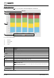

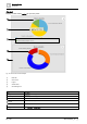


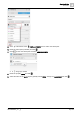

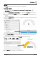

Table Of Contents
- 1 About this document
- 2 Commissioning
- 2.1 Default connection
- 2.2 Initial login
- 2.3 Setup wizard
- 2.4 Discover and assign devices
- 2.5 Subscribing to the time master
- 2.6 Time synchronization of the time master
- 2.7 Registering as a foreign device
- 2.8 Touch panel settings
- 2.9 Operating and monitoring features
- 3 Data point integration
- 4 Graphic features
- 4.1 Plant view Tools
- 4.2 Kiosk graphics
- 4.3 Engineering notations
- 5 Graphics Builder
- 5.1 Overview
- 5.2 Pane tools
- 5.3 Graphics libraries
- 6 Graphics engineering
- 6.1 Using supersample graphics
- 6.2 Optimizing graphics for PXM touch panels and standard devices
- 6.3 Thumbnails
- 6.4 Dashboards
- 7 Advanced functionality
- 8 Tips and tricks
- 8.1 Updates required after a time zone change
- 8.2 APPLY BATCH TAGS
- 8.3 Graphic components within models cannot be modified
- 8.4 A graphic with relative binding that includes data points from different branches of the hierarchy cannot be created at the Root level
- 8.5 Relative hyperlinks cannot be added to a graphic at the Root level
- 8.6 Relative hyperlinks in a graphic are broken if the graphic is engineered offline and then imported to another device
- 8.7 Automatic logout from Desigo Control Point causes Graphics Builder to temporarily stop working
- 8.8 Detection of network interruptions
- 8.9 Cancelling a kiosk log out sequence
- 8.10 Special characters do not display in graphic file names
- 8.11 The color of a graphical component may display incorrectly if the component was copied
- Index

Graphics Builder
Pane tools
5
A6V11604297_en--_g
89 | 195
GAUGE
A GAUGE displays the current value of a virtual point in a gauge format.
Configuring a GAUGE
This procedure uses the PROPERTIES, COMPONENTS, VIRTUAL POINTS and
EQUIPMENTS panes.
1. From the COMPONENTS > COMPONENTS pane, drag-and-drop GAUGE onto the work area.
2.
(Optional)
Select the new GAUGE and use the BASIC PROPERTIES to modify the appearance of
the gauge.
Working with gauges [➙ 167]
3. From the EQUIPMENTS pane, drag-and-drop a numeric point onto the work area to create a smart
label for the gauge.
4. In the VIRTUAL POINTS pane, locate the virtual point associated with the numeric point that was
used to create the smart label.
5. Drag-and-drop the new virtual point onto the GAUGE to bind it to the component.
6. Click PREVIEW in the upper right corner to display the gauge.