
User Manual

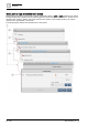


Table Of Contents
- 1 About this document
- 2 Commissioning
- 2.1 Default connection
- 2.2 Initial login
- 2.3 Setup wizard
- 2.4 Discover and assign devices
- 2.5 Subscribing to the time master
- 2.6 Time synchronization of the time master
- 2.7 Registering as a foreign device
- 2.8 Touch panel settings
- 2.9 Operating and monitoring features
- 3 Data point integration
- 4 Graphic features
- 4.1 Plant view Tools
- 4.2 Kiosk graphics
- 4.3 Engineering notations
- 5 Graphics Builder
- 5.1 Overview
- 5.2 Pane tools
- 5.3 Graphics libraries
- 6 Graphics engineering
- 6.1 Using supersample graphics
- 6.2 Optimizing graphics for PXM touch panels and standard devices
- 6.3 Thumbnails
- 6.4 Dashboards
- 7 Advanced functionality
- 8 Tips and tricks
- 8.1 Updates required after a time zone change
- 8.2 APPLY BATCH TAGS
- 8.3 Graphic components within models cannot be modified
- 8.4 A graphic with relative binding that includes data points from different branches of the hierarchy cannot be created at the Root level
- 8.5 Relative hyperlinks cannot be added to a graphic at the Root level
- 8.6 Relative hyperlinks in a graphic are broken if the graphic is engineered offline and then imported to another device
- 8.7 Automatic logout from Desigo Control Point causes Graphics Builder to temporarily stop working
- 8.8 Detection of network interruptions
- 8.9 Cancelling a kiosk log out sequence
- 8.10 Special characters do not display in graphic file names
- 8.11 The color of a graphical component may display incorrectly if the component was copied
- Index

Graphics Builder
Overview
5
A6V11604297_en--_g
61 | 195
How semantic tags create structure in the system
Desigo Control Point uses a semantic tagging model, which is based on the open source Project Haystack
model. Rather than object instance numbers or proprietary data point names, a
semantic tagging model
uses
standardized, descriptive metadata to categorize and interpret data point information.
The Haystack tags site, equip and point create a basic hierarchy in Desigo Control Point. The following figure
outlines how these tags are used in the context of a building hierarchy.
①
site
The site tag represents a building or other type of facility with a unique street address. In this example,
both Building and Default site have a site tag.
②
equip
The equip tag represents an equipment asset, which is often a physical asset, such as an AHU, boiler,
or chiller. An equip tag can also be used for a logical grouping, such as a chiller plant.
equip objects are structured and can have references to other equip objects or to site objects. In this
example:
● Cooling coil has a parent equip reference (equipRef) to Air handling unit West Wing.
● Air handling unit West Wing has a parent equip reference (equipRef) to Vent & air cond.plants.
● Vent & air cond.plants has a parent site reference (siteRef) to Building.
③
point or shadowPoint
Every data point in the system has a point or shadowPoint tag.
Point or shadowPoint objects are not structured and have references to a parent equip or site object.
In this example, Valve is an analog output point and has a parent equip reference (equipRef) to
Cooling coil.
Each data point also has one of the following tags to classify its type:
● cmd, which classifies a data point as an output, AO/BO, command, or actuator.
● sensor, which classifies a data point as an input, AI/BI, or sensor.
● sp, which classifies a data point as a setpoint, soft point or process control variable.
Note
A best practice when working with binding queries is to use (point or shadowPoint) to cover both
possible cases and accommodate future enhancements.