
Data Sheet for Product

3
Siemens Schweiz AG A6V11646020_en--_f
Smart Infrastructure 2022-02-18
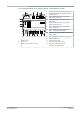
Technical and mechanical design
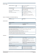
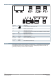
The compact build allows for mounting the devices on a standard rail or a wall.
1
2
3
4
5
6
7
8
910
11 12
13
14
15 16
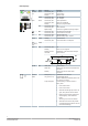
Date/Series
S/N
WLAN
Default
10
11
4 Service button (network login and WLAN on/off)
5 2-port Ethernet switch with 2 LEDs per port for
display purposes
6 Plug-in terminal block with screw terminals
KNX, PL-link, for future use
7 Plug-in terminal block with screw terminals
Power supply
8 Plug-in terminal blocks with screw terminals
Digital input, for future use
9 Plug-in terminal block with screw terminals
M-bus, for future use
10 Plug-in terminal block with screw terminals
COM1 / COM2 (MS/TP or Modbus)
11 DIP switches for bus termination and polarization
COM1 / COM2
12 Slider for mounting on standard mounting rails
13 Eyelets for cable ties
1 Plastic housing 14 Holes for wall mounting
2 Front cover 15 Date / Series and Serial number
3 LEDs for communication and state 16 QR code for default WLAN access
Description see Technical data