Desigo™ Automation stations PXC4.
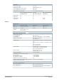
Type summary Type Order number Description PXC4.M16 S55375-C101 Compact automation station for BACnet MS/TP with Modbus PXC4.M16S S55375-C109 Compact automation station for BACnet MS/TP Inputs/outputs PXC4.M16 PXC4.
Functions Automation stations for HVAC and building control systems. ● System functions (alarming, scheduling, trending, access protection with individually definable user profiles and categories) ● Freely programmable (close resemblance to CEN standard 11312). All function blocks, available in libraries, can be graphically connected.
LED displays Activity LED Color Activity Function RUN Green Continuously ON Continuously OFF Flashing Device operational Device not operational Start-up or program halted Red Continuously OFF Continuously ON Rapid flashing OK HW or SW fault Firmware or application missing/corrupted MSTP Yellow Flashing Continuously OFF Communication BACnet MS/TP No communication COM TX Yellow Flashing Continuously OFF Communication No communication to subsystem Continuously OFF Flashing OK Device is not
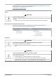
Product documentation Related documents such as the environmental declarations, CE declarations, etc., can be downloaded from the following Internet address: www.siemens.com/bt/download Notes Safety CAUTION National safety regulations Failure to comply with national safety regulations may result in personal injury and property damage. ● Observe national provisions and comply with the appropriate safety regulations.
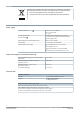
Disposal The device is considered an electronic device for disposal in accordance with European Directive and may not be disposed of as domestic waste. ● Use only designated channels for disposing the devices. ● Comply with all local and currently applicable laws and regulations.
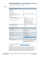
Interfaces Screw terminals, plug-in Cu-wire or Cu-strand with wire end sleeve 1 x 0.6 mm ∅ to 2.5 mm2 (22 to 14 AWG) or 2 x 0.6 mm ∅ to 1.0 mm2 (22 to 18 AWG) Cu-strand without wire end sleeve 1 x 0.6 mm ∅ to 2.5 mm2 (22 to 14 AWG) or 2 x 0.6 mm ∅ to 1.5 mm2 (22 to 16 AWG) Stripping length 6...7.5 mm (0.24...0.29 in) Screwdriver Slot screws, screwdriver size 1 with shaft ø = 3 mm Max. tightening torque 0.6 Nm (0.
On PXC4.M16 Modbus RTU interface Interface type EIA-485, electrically isolated Baud rate 1200, 2400, 4800, 9600, 19200, 38400, 57600, 115200 (depending on the configuration) Internal bus termination 120 Ohm, switchable with DIP switch Internal bus polarization 270 Ohm pull-up/pull-down resistances, switchable with DIP switch Cabling (in-house cabling only) 3-wire cable, shielded cable recommended (shield has to connected to building earth in the mounting panel) Cable length Max.
Digital input Contact query voltage 21.5...25 V Contact query current 1 mA; 6 mA initial current Contact resistance for closed contacts Max. 200 Ω Contact resistance for open contacts Min. 50 kΩ Counter memory (counter inputs 0 ... 4.3 x 10⁹ (32-bit counter) Min. closing/operating time [ms] including bounces Of which Max. bounce time [ms] Max.
Field device supply (I/O modules TXM) AC 24 V (terminal V~ on the I/O modules TXM) Max. 2 A, short-circuit proof *) *) Sum total onboard V~ and TXM bus V~ max.
particular installation. If this equipment does cause harmful interference to radio or television reception, which can be determined by turning the equipment off and on, the user is encouraged to try to correct the interference by one or more of the following measures: ● Reorient or relocate the receiving antenna. ● Increase the separation between the equipment and receiver. ● Connect the equipment into an outlet on a circuit different from that to which the receiver is connected.
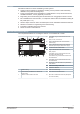
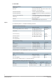
Connection terminals 8 9 3 5 4 65 66 67 6 7 68 69 70 Terminal Symbol Description 3, 4 KNX PXC4.M16: KNX PL-Link (for future use) 5, 6 24 V ~, ⏊ Operating voltage AC 24 V 7 Module Channel 61 1…12 11 1…4 Functional ground (must be connected on the installation side with the building grounding system (PE). 8 to 29 Ux Universal inputs/outputs ⏊ Measuring ground for Ux 8, 19 V+ DC 24 V power for field devices 2.
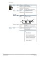
Analog inputs M Ux B1 Temperature sensor LG-Ni 1000 B2 Temperature sensor, general B3 Resistance transmitter B4 Active sensor powered by the automation station B5 Active sensor with external power Do NOT ground external power (ground loops) B6 Active sensors 0 ... 20 mA or 4 ... 20 mA (2-wire) On U1, U2, U7, U8 only Y1 Device with input DC 0...10 V Y2 General device with control input DC 0...10 V, Powered by the automation station Y3 General device with control input DC 0...
Dimensions All dimensions in mm and inches. PXC4.M16 49 (1.91") 4.1 (0.16") 45 (1.77") 110 (4.33") 7 (0.28") 67 (2.64") 183 (7.20") 70.5 (2.78") 124 (4.88") 3 (0.12") 117 (41.61") 198 (7.80") 26.5 (1.04") PXC4.M16 with TXM module 64 (2.52") 7 (0.28") 90 (3.54") 198 (7.80") 269 (10.59") Issued by Siemens Switzerland Ltd Smart Infrastructure Global Headquarters Theilerstrasse 1a CH-6300 Zug +41 58 724 2424 www.siemens.