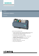
Desigo™ Automation stations PXC4.
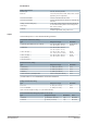
Type summary Type Order number Description PXC4.E16 S55375-C100 Compact automation station for BACnet/IP and BACnet/SC with Modbus PXC4.E16S S55375-C108 Compact automation station for BACnet/IP and BACnet/SC Inputs/outputs PXC4.E16 PXC4.
Desigo Control Point Description Type BACnet touch panels with integrated Web server Data sheet A6V11664137 7.0 " PXM30.E 10.1 " PXM40.E 15.6 " PXM50.E Client Touch Panels with data storage in Web server PXG3.Wx00-1: A6V11664139 7.0 " PXM30-1 10.1 " PXM40-1 15.6 " PXM50-1 BACnet/IP Web server with standard functionality PXG3.W100-1 BACnet/IP Web server with extended functionality PXG3.
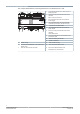
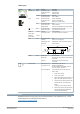
Technical and mechanical design The compact build allows for mounting the devices on a standard rail or a wall. 5 4 3 6 7 4 2-port Ethernet switch with 2 LEDs per port for display purposes 5 PXC4.
LED displays Activity LED Color Activity Function Ethernet 1/2 Green Continuously ON Continuously OFF Flashing Link active No connection Network traffic Yellow Continuously ON Continuously OFF Link 100 Link 10 Mbps Green Continuously ON Continuously OFF Flashing Device operational Device not operational Start-up or program halted Red Continuously OFF Continuously ON Rapid flashing OK HW or SW fault Firmware or application missing/corrupted Blue Continuously ON Continuously OFF Connection
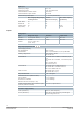
Notes Safety CAUTION National safety regulations Failure to comply with national safety regulations may result in personal injury and property damage. ● Observe national provisions and comply with the appropriate safety regulations. Mounting position and ambient temperature The devices can be snapped onto standard rails or screwed onto a flat surface. Plug-in screw terminals connect power and interfaces. Ambient temperature -5...50 °C (23...122 °F) Ambient temperature -5...45 °C (23...
Technical data Power supply Operating voltage (24 V~, ⏊, ) AC 24 V -15 / +20 % (PELV) AC 24 V Class 2 (US) 48…63 Hz Functional ground (US) Functional earth The terminal for the functional ground must be connected on the installation side with the building grounding system (PE). Screw terminals for wire cross sections up to Max. 2.5 mm2 (14 AWG) Internal fusing 4 A irreversible / non-replaceable External supply line fusing (EU) Non-renewable fuse max. 10 A slow-blow or circuit breaker max.
Interfaces Screw terminals, plug-in Cu-wire or Cu-strand with wire end sleeve 1 x 0.6 mm ∅ to 2.5 mm2 (22 to 14 AWG) or 2 x 0.6 mm ∅ to 1.0 mm2 (22 to 18 AWG) Cu-strand without wire end sleeve 1 x 0.6 mm ∅ to 2.5 mm2 (22 to 14 AWG) or 2 x 0.6 mm ∅ to 1.5 mm2 (22 to 16 AWG) Stripping length 6...7.5 mm (0.24...0.29 in) Screwdriver Slot screws, screwdriver size 1 with shaft ø = 3 mm Max. tightening torque 0.6 Nm (0.
On PXC4.E16 Modbus RTU interface Interface type EIA-485, electrically isolated Baud rate 1200, 2400, 4800, 9600, 19200, 38400, 57600, 115200 (depending on the configuration) Internal bus termination 120 Ohm, switchable with DIP switch Internal bus polarization 270 Ohm pull-up/pull-down resistances, switchable with DIP switch Cabling (in-house cabling only) 3-wire cable, shielded cable recommended (shield has to connected to building earth in the mounting panel) Cable length Max.
Digital input Contact query voltage 21.5...25 V Contact query current 1 mA; 6 mA initial current Contact resistance for closed contacts Max. 200 Ω Contact resistance for open contacts Min. 50 kΩ Counter memory (counter inputs 0 ... 4.3 x 10⁹ (32-bit counter) Min. closing/operating time [ms] including bounces Of which Max. bounce time [ms] Max.
Field device supply (I/O modules TXM) AC 24 V (terminal V~ on the I/O modules TXM) Max. 2 A, short-circuit proof *) *) Sum total onboard V~ and TXM bus V~ max.
particular installation. If this equipment does cause harmful interference to radio or television reception, which can be determined by turning the equipment off and on, the user is encouraged to try to correct the interference by one or more of the following measures: ● Reorient or relocate the receiving antenna. ● Increase the separation between the equipment and receiver. ● Connect the equipment into an outlet on a circuit different from that to which the receiver is connected.
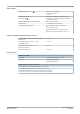
Connection terminals 8 9 3 5 4 6 7 68 69 70 Terminal Symbol 1, 2 Description Module Channel 61 1…12 11 1…4 2 x RJ45 interface for Ethernet with switch 3, 4 KNX PXC4.E16: KNX PL-Link (for future use) 5, 6 24 V ~, ⏊ Operating voltage AC 24 V 7 Functional ground (must be connected on the installation side with the building grounding system (PE). 8 to 29 Ux Universal inputs/outputs ⏊ Measuring ground for Ux 8, 19 V+ DC 24 V power for field devices 2.
Analog inputs M Ux B1 Temperature sensor LG-Ni 1000 B2 Temperature sensor, general B3 Resistance transmitter B4 Active sensor powered by the automation station B5 Active sensor with external power Do NOT ground external power (ground loops) B6 Active sensors 0 ... 20 mA or 4 ... 20 mA (2-wire) On U1, U2, U7, U8 only Y1 Device with input DC 0...10 V Y2 General device with control input DC 0...10 V, Powered by the automation station Y3 General device with control input DC 0...
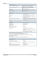
Dimensions All dimensions in mm and inches. PXC4.E16 49 (1.91") 4.1 (0.16") 45 (1.77") 110 (4.33") 7 (0.28") 67 (2.64") 183 (7.20") 70.5 (2.78") 124 (4.88") 3 (0.12") 117 (41.61") 198 (7.80") 26.5 (1.04") PXC4.E16 with TXM module 64 (2.52") 7 (0.28") 90 (3.54") 198 (7.80") 269 (10.
Issued by Siemens Switzerland Ltd Smart Infrastructure Global Headquarters Theilerstrasse 1a CH-6300 Zug +41 58 724 2424 www.siemens.com/buildingtechnologies Document ID A6V11646018_en--_g Edition 2022-02-18 © Siemens Switzerland Ltd, 2020 Technical specifications and availability subject to change without notice.