
Operating Instructions


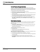
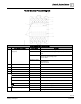

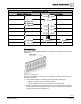


Table Of Contents
- Cyber security disclaimer
- How to Use This Manual
- Chapter 1—Introduction
- Chapter 2—Hardware Features
- 16- and 24-Point Compact Series Diagram
- 36-Point Compact Series Product Diagram
- Supported Point Types
- Compact Series Backup Batteries
- Memory
- Communication Connections
- Compact Series Specifications
- BACnet Compact Series Specifications
- Compact Series Smoke Control Application Requirements
- HOA (Hand-Off-Auto) Upgrade Kits
- PXC Compact on P1
- PXM10S/T Product Overview and Description
- Unitary Equipment Controller
- TX-I/O Product Range Overview
- PX Series Enclosures and Service Boxes
- Chapter 3—Applications
- Chapter 4—Troubleshooting
- Glossary
- Index

Chapter 2—Hardware Features
TX-I/O Product Range Overview
0
85 |
118
Siemens Industry, Inc.
Owner's Manual
553-104
Building Technologies
2018-10-01
TX-I/O Module Product Diagram
TX-I/O Module Symbols and Status LEDs
LED, Symbol, or Feature
LED or Symbol
Indication
1
Address key and module status
LED (green)
-
Module status as a whole (as opposed to the I/O points).
ON
Normal operation. 24 Vac (supply voltage) input present; fuse is
intact.
OFF
Error.
- No 24 Vac (supply voltage) input.
- Fuse is blown.
Flashing or pulsing
- Fault indication
- No address key
- Remote override
2 I/O point numbers
-
-
3 Terminal number
-
-
4 Test terminal
-
5 Connection terminals
-
6
-
System neutral.
-
Configurable point.
-
Output (arrow pointing OUT from center of module).
-
Input (arrow pointing IN toward center module).
-
24 Vdc output (field supply).
-
24 Vac output (field supply).
7 Override status LEDs (yellow)
ON
Manual operation; a local override is active.
OFF
No voltage or manual operation off.
The picture can't be displayed.