
Installation Instructions


Document No. 553 -085
Installation Instructions
December 22, 2005
Siemens Building Technologies, Inc. Page 3 of 4
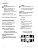
24 Vac
RS-485
ALN Ethernet ALN
External Sensor Power
Cover Mounting Holes
Use Provided 1-3/4" Screws
Slide Out Mounting Tabs
Use Provided 3/8" or 3/4" screws
NOTE: Both ALN
ports are not
available on the
same model.
6.27"
(159.23 mm)
6.16"
(156.5 mm)
Human-
Machine
Interface
Port
24V
37 38 39 40
24V 24V
ALN
RUN
FAULT
LOW BATT
COMM
HMI
123
PXC0005R1
NOTE: The RUN LED
is on solid during
normal operation.
Figure 2. Front View of the PXC Compact Controller (PXC24 shown).
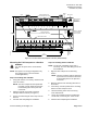
Mounting the PXC Compact on a Surface
WARNING:
Turn OFF AC power at the circuit breaker
panel.
NOTE: This option is for energy management only
(low voltage (Class 2) and non-smoke
control applications).
Steps for Installing with a DIN Rail
1. Using wall anchors, if necessary, attach the DIN
rail to the surface.
NOTE: The PXC Compact must be positioned
to provide a 3-inch minimum clearance
for terminating wires to the ports and
connectors.
2. Align the channel on the back of the PXC
Compact with the DIN rail (see Figure 1).
3. Push in each mounting tab until it clips onto the
DIN rail.
4. Continue with Completing the Installation.
Steps for Installing without a DIN Rail
NOTE: Use the 3/4” self-drilling screws and, if
necessary, the 1-3/4” self-drilling screws for
this installation.
1. Align the PXC Compact on the mounting
surface.
NOTE: The PXC Compact must be positioned
to provide a 3-inch minimum clearance
for terminating wires to the ports and
connectors.
2. Mark the position of the mounting tab holes on
the surface.
3. If necessary, mark the position of the mounting
holes in the PXC Compact cover.
4. Drill the mounting holes and, if necessary,
insert wall anchors.
5. Secure the controller using the provided 3/4”
screws and, if necessary, the 1-3/4” screws.
6. Continue with Completing the Installation.