
Operating Instructions
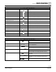
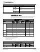
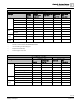
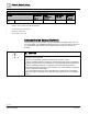
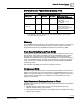
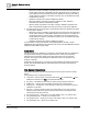
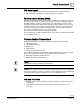
Table Of Contents
- Cyber security disclaimer
- How to Use This Manual
- Chapter 1—Introduction
- Chapter 2—Hardware Features
- 16- and 24-Point Compact Series Diagram
- 36-Point Compact Series Product Diagram
- Supported Point Types
- Compact Series Backup Batteries
- Memory
- Communication Connections
- Compact Series Specifications
- BACnet Compact Series Specifications
- Compact Series Smoke Control Application Requirements
- HOA (Hand-Off-Auto) Upgrade Kits
- PXC Compact on P1
- PXM10S/T Product Overview and Description
- Unitary Equipment Controller
- TX-I/O Product Range Overview
- PX Series Enclosures and Service Boxes
- Chapter 3—Applications
- Chapter 4—Troubleshooting
- Glossary
- Index

Chapter 2—Hardware Features
36-Point Compact Series Product Diagram
0
31 |
118
Siemens Industry, Inc.
Owner's Manual
553-104
Building Technologies
2018-10-01
PXC-36 Features, Symbols, and Status LEDs.
Terminal Block Connection
Label
Indicates
3
Functional earth.
4 through 27
Digital Output relay.
A
10B/100B Ethernet port.
B
USB Device port.
30, 32, 33, 35, 36, 38
Super Universal (+). (X1 through X6)
31, 34, 37
–
Signal Common.
39, 41, 50, 52, 53, 55, 56, 58, 59, 61, 62,
64, 65, 67, 68, 70, 71, 73
Universal Input/Output (+). (U7 through U24)
40, 51, 54, 57, 60, 63, 66, 69, 72
–
Signal Common.
42, 44, 46, 48
24 Vdc external sensor power (+) source.
43, 45, 47, 49
–
Signal Common.
74, 76, 77, 79
Digital Input (+). (DI25 through DI28)
75, 78
–
Signal Common
82 through 84
CD CS
Island Bus Communication
85 through 87 and 88 through 90
+ –
RS-485 port.
C
USB Host port
D
HMI
Human-Machine Interface port
PXC-36 Features, Symbols, and Status LEDs.
Status LEDs
Label
Indicates
RUN LED
RUN
(green)
ON - Normal steady Green, unit is powered and running.
OFF - Error.
FAULT LED
FAULT
(red) (for future
use)
Normal Off, not currently implemented. May be Red if processor
does not complete boot.
LOW BATT LED
LOW BATT
(red)
ON - Error.
OFF - Normal operation.
COMM LED
COMM
(yellow)
ON – Linked to Ethernet network.
OFF - No link to Ethernet network.
Flashing indicates communicating with Ethernet network.
RS-485 TX
A TX
(yellow)
Flashing - Transmitting information over RS-485 P1 (FLN 1) or
MS/TP FLN.
B TX
(yellow)
Flashing - Transmitting information over RS-485 P2 or BACnet
MS/TP ALN or P1 (FLN 2) (depending on how the port is
defined).
A TX
or
B TX
OFF or ON solid - No device, no connection, or bad connection.