
Installation Instructions

Document No. 553-168
Installation Instructions
November 03, 2017
Page 2 of 4 Siemens Industry, Inc.
Prerequisites
CAUTION:
No power wiring is connected to the PXC
Compact at this time.
If mounting in an enclosure:
Enclosure is installed.
The power source is installed, as applicable.
The power is OFF.
All necessary wiring is pulled and terminated per
the layout drawing.
Power and communication wiring is terminated to
the removable plugs supplied with the devices.
CE Compliance Requirements
Must be installed inside a metal enclosure rated at IP20
minimum.
Energy Management Applications
For energy management only (low voltage Class 2), the
PXC Compact may be mounted on a flat surface.
Applications Requiring a Secure Enclosure
Mount the PXC Compact inside a listed enclosure along
with a Service Box and Sidewall Kit, if needed.
Smoke Control Application
Requirements
CAUTION:
The 115V or 230V PX Series Service Box is
required for UL864 and NFPA92A compliant
installations. For more information, see the
PX Series Service Box Assemblies
Installation Instructions (553-131).
For non-UL864 and non-NFPA92A
applications, any 24 Vac UL Listed Class 2
transformer may be used.
NOTE: For smoke control applications over Ethernet or
BACnet/IP, the PXC Compact must be
connected to the Automation Level Network
(ALN) through an Ethernet switch that is UL
Listed for Fire Signaling. ALN and FLN circuits
are supervised.
For smoke control applications, mount the PXC Compact
inside a 19" or 34" PX Series enclosure (PXA-ENC19 or
PXA-ENC34). For more information, see the 19" and 34"
PX Series Enclosure Assemblies Installation Instructions
(553-130).
Service Modem Kit (538-915) is required for remote
connection to the HMI of a PXC Compact running smoke
control applications. The modem, serial cable, and surge
suppressor must be installed inside the 19" or 34" PX
Series Enclosure with a Service Box.
For Ethernet communications, the UL Listed surge
protector (Ditek model DTK-MRJ45C5E) is required for
Ethernet or BACnet/IP networks. The surge protector
must be located in the same enclosure as the controller.
Installation Instructions
WARNING:
Turn OFF AC power at the circuit breaker
panel.
CAUTION:
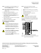
UL Listings require that NEC Class I and
Class II wiring be kept separate from each
other. Use separate conduit and cable tie
bars to separate Class I DO wires from all
other Class II wiring.
NOTE: Securely fasten the PXC Compact so that it
does not come loose when point connectors are
removed.
NOTE: If you need to reinsert one of the mounting tabs,
see the PXC Compact Series Owner’s Manual
(553-104) for instructions.
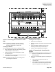
The PXC Compact may be mounted either vertically
(with 24 Vac and DOs on the right) or horizontally (with
24 Vac and DOs at the top).
Options for Mounting the PXC Compact
Select one of the following options for installation:
Mount the controller on a DIN rail by using the
four slide-out mounting tabs.
Fasten the controller to a surface or enclosure
backplane with screws