
Data Sheet for Product


12/18
Siemens PXC….D – Automation stations, compact model CM1N9215en_25
Smart Infrastructure 2022-01-15
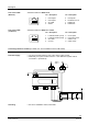
PXC22.1-E.D
1, 2
24 V ~,
Operating voltage AC 24 V
3 Functional earth
CFC IOAddr
4 … 21 DO1 … DO6 6 Digital outputs (Relays)
DO1: C=5.1
30 ... 38
U1 … U6
6 Universal inputs / outputs with Q250
xx1: C=4.1 *)
39 ... 61
U7 … U16
10 Universal inputs / outputs
xx7: C=1.1 *)
80, 81
CP+, CP
–
PPS2 bus (for up to 5 QAX... room units)
82 ... 84
, CD, CS Island bus: Additionally, the system neutral conductor
of the
island bus system must be connected to
(Terminal 82).
A
Ethernet socket
C
HMI
RJ45 socket for PXM10
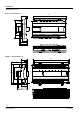
PXC36.1-E.D
1, 2
24 V ~,
Operating voltage AC 24 V
3 Functional earth
CFC IOAddr
4 … 27 DO1 … DO8 8 Digital outputs (Relays)
DO1: C=5.1
30 ... 38
U1 … U6
6 Universal inputs / outputs with Q250
xx1: C=4.1 *)
39 ... 73
U7 … U24
18 Universal inputs / outputs
xx7:
C=1.1 *)
74 ... 79 DI1 … DI4 4 Digital inputs
DI1: C=3.1
80, 81
CP+, CP
–
PPS2 bus (for up to 5 QAX... room units)
82 ... 84
, CD, CS Island bus: Additionally, the system neutral conductor
of the
island bus system must be connected to
(Terminal 82).
A
Ethernet socket
C
HMI
RJ45 socket for PXM10
*) Signal type when no application is loaded (wiring test):
U1…U6: xx = Y10S, U7…U24: xx = R1K
Observe the technical data for the relay outputs.
Local installation regulations must be observed.
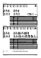
DO1
U1 U2 U3 U4
U5 U6 U7 U8
U9 U10 U11 U12
U13 U14 U15 U16
DO1
U1 U2 U3 U4
U5 U6U7 U8
U9 U10 U11 U12
U13 U14 U15 U16
U17
U18
U19
U20
U21
U22
U23
U24
STOP
Caution!