
Installation Instructions


Document No. A5W00125545
Installation Instructions
September 8, 2020
Information in this document is based on specifications believed correct at the time of publication. The right is reserved to make changes as design
improvements are introduced. APOGEE and Insight are registered trademarks of Siemens Industry, Inc. Desigo® and Desigo® CC are registered
trademarks of Siemens Schweiz AG. Other product or company names mentioned herein may be the trademarks of their respective owners. © 2020
Siemens Industry, Inc. All presented offerings are subject to a cyber security disclaimer which is available at: www.siemens.com/bt/cyber-security.
Siemens Industry, Inc.
Smart Infrastructure
1000 Deerfield Parkway
Buffalo Grove, IL 60089-4513
USA
Tel. 1 + 847-215-1000
Your feedback is important to us. If you have comments
about this document, please send them to
SBT_technical.editor.us.sbt@siemens.com.
Document No. 553-638-DC
Printed in the USA
Page
4 of 4
Installing the DIN Rail
NOTE:
Allow a minimum clearance of 3 inches (7.6 cm)
around the field panel ports and connectors for
terminating wires.
NOTE:
For longer DIN rails, use one mounting screw
per running foot of DIN rail.
Do the following if the DIN rail is not already installed:
1. Align and level the DIN rail on the mounting surface
or enclosure backplane.
2. Mark the position of the mounting holes at either end
of the DIN rail.
3. Using wall anchors, if necessary, attach the DIN rail
to the surface or backplane.
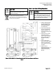
Installing the PXC Modular, BCM and TX-I/O
1. Install the PXC Modular on the DIN rail.
2. (Optional) Plug FLN Expansion Module on PXC
Modular Expansion connector and DIN rail.
3. Install Bus Connection Module (BCM) attached to
PXC Modular bus connector and DIN rail adding
wired TX-I/O module bases to self-forming bus and
up to one additional BCM where needed.
4. (Optional) Install a BCM at the top of second DIN rail
adding wired TX-I/O module bases to self-forming
bus and up to one additional BCM where needed.
5. Insert each TX-I/O module fully in its base, insert
module label and address key per layout.
6. (Optional) Install Bus Expansion Module (TXA1.IBE)
between first BCM and TX-I/O in primary panel with
BM OFF, between first BCM and TX-I/O in each
secondary panel with BM ON, and set EOL
terminators ON at first and last IBE on network.
Installing Connector Covers (If required)
◈
Install TX-I/O bus covers from Controller or Bus
Connection Module carton on TX-I/O Module or
BCMconnector at either end of self-forming bus
For more information, see the
TX-I/O Module Installation
Instructions
(553-141).
Connecting the Power and Communication
Wires
NOTE:
Do not connect BACnet I/P or MS/TP ALN
communication cable into the PXC Modular until
start-up is complete.
1. Plug in Power on PXC Modular.
2. (Optional) Plug in MS/TP or P1 FLN to RS-485 port
on PXC Modular and/or FLN Expansion Module.
3. Plug in Power and Communication on each BCM.
4. (Optional) Plug in Communication (CD) to BCM on
second self-forming bus (DIN rail).
5. (Optional) Plug in RS-485 Communication on primary
IBE and each secondary IBE. Repeat steps 3 and 4
for BCM in each secondary panel.
Completing the Installation
1. Ensure that AC power to PSU is turned ON at the
circuit breaker panel, typically VIN to one of the PSU
will be off during A/B operation.
2. Turn PSU power switch ON.
3. Verify PSU LEDs are ON.
4. Verify each BCM field bus LED is ON (4A fuse).
5. Verify TX-I/O Module LEDs are ON (1.6A PTC).
6. Adjust Voltage on PSU for 24 Vdc at first installed
TXM1.8X(-ML) Terminals 3 (+) and 2 (-).
7. Verify PXC Modular Run LED is ON.
8. Repeat steps 1 to 7 for PSU-B with B power ON or
may temporarily connect PSU-A plug to PSU-B.
9. Repeat steps 1 to 8 in any secondary panels
verifying COM LED ON for each TXA1.IBE.
The installation is now complete.