
Installation Instructions


Document No. A5W00125545
Installation Instructions
September 8, 2020
Siemens Industry, Inc. Page 3 of 4
CAUTION
Do not install the PXC Modular on a
vibrating surface (for example, an air
handler or ductwork).
This device includes electrical and electronic
components and must not be disposed of as domestic
waste. Product recovery and disposal must comply with
all national and local regulations.
Class 1 and Class 2 Wiring Separation
CAUTION
UL Listings require that NEC Class I and
Class II wiring be kept separate from each
other. Use separate conduit and cable tie
bars to separate Class I Digital Output (DO)
wires from all other Class II wiring.
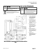
● Shown A/B Redundant
24 Vdc 20A PSU with
Diode Coupler for TX-
I/O powered through
four TXS1.EF4.
● Option A/B Redundant
24 Vdc 10A PSU with
Diode Coupler for TX-
I/O powered through two
TXS1.EF4.
● Option layout for each
Secondary Panel is
same except use IBE in
place of PXC100 and
add IBE in Primary
Panel.
● Option single panel
power source with single
PSU or two PSU with
power sharing (no Diode
Coupler).
● Option remove
Expansion Bus cover on
top of PXC100 and
install FLN Expansion
Module.
Figure 1: PXC100-E96-DC.A Modular Controller with 24 Vdc Power Conversion in Primary
Panel