
User Manual


4 / 10
Siemens PXC001 System controllers CM1N9223en_09
Smart Infrastructure 2020-05-30
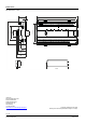
The terminal blocks are removable for easy wiring.
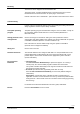
Communication
RS232/RS485: RX (Green) TX (Yellow)
KNX: RX (Green) TX (Yellow) Service (Red)
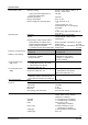
The other LEDs have the following meaning:
Service pin
LED
Color
Activity
Function
RUN
Green
Continuously ON
Continuously OFF
Power OK
No power
FAULT
Red
Continuously OFF
Continuously ON
Rapid flashing
OK
Fault
Firmware missing / corrupt
LOW BATT
Red
Continuously OFF
Continuously ON
Battery OK
Battery empty– replace!
COMM
Red
Continuously ON
Continuously OFF
Flashing
Connection to switch OK
No connection to switch
Communication
INFO
Red
Freely programmable
SERVICE
(Ethernet,
PXC001-E.D)
Red
Continuously OFF
Continuously ON
Flashing
Flashing per wink
command *)
OK
No connection to switch or
DHCP Server
No IP address configured
Physical identification of system
controller after receipt of wink
command
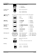
SERVICE
(LonTalk,
PXC001.D)
Red
Continuously OFF
Continuously ON
Flashing
Flashing per wink
command *)
LONWORKS node is configured
Faulty LONWORKS chip, or service
pin currently depressed
LONWORKS node is not configured
Physical identification of system
controller after receipt of wink
command
*)
Wink command pattern:
2s
1s
21s
5 Hz 5 Hz
9222z02
2s
1s
Identification of the system controller in the IP network or LONWORKS network
See "Commissioning".
Engineering
See the PX open documents CM110761.
Depending on the bus topology, a 120 Ohm resistor must be connected.
Terminal blocks
LED indicators
Service pin
Workflow
Bus terminating
resistor for RS485