
Installation Instructions


Document No. 553-130
Installation Instructions
August 31, 2013
Siemens Industry, Inc. Page 3 of 6
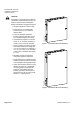
DOOR CLEARANCE
DOOR CLEARANCE
Minimum of 28" (711 mm)
from wall to nearest object.
Otherwise, remove door.
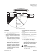
FIELD PANEL TOP
6"
(153 mm)
NEAREST OBJECT
5.00" (127 mm)
FROM RIGHT
OF PANEL,
ANY DEPTH
FROM WALL
1" GRID
(25 mm)
22"
(559 mm)
Minimum 19" to
Perpendicular Wall
NEAREST OBJECT
5.00" (127 mm)
FROM LEFT OF PANEL
7.00" (178 mm)
OUT FROM WALL
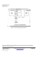
CAUTION
ATTENTION
- Leave a minimum of 2" (50.8 mm) between top of enclosure and wiring
trough and at least 5" (127 mm) between individual cabinets.
- Laissez un minimum de 2" (50.8 mm) entre le haut de l’armoire et le
faisceau de cables et un minimum de 5" (127 mm) entre les armouires individuelles.
CAUTION
ATTENTION
- Leave a minimum of 2" (50.8 mm) between top ofenclosure and wiring
trough and at least 5" (127 mm) between individual cabinets.
- Laissez un minimum de 2" (50.8 mm) entre le haut de l’armoire et le
faisceau de cables et un minimum de 5" (127 mm) entre les armouires individuelles.
TXIO0013R1
135
40
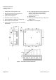
Figure 3. Spacing Requirements.
Installation
NOTE: Follow all safety regulations and local codes
when installing this equipment.
1. Determine the mounting location of the enclosure
using the spacing requirements shown in Figure 3
and Figure 6. See Figure 4 and Figure 5 for panel
dimensions.
Minimum spacing between the panel and any
left (hinged side) obstruction is 1 inch spacing
for every 1 inch of depth, starting at 5 inches
(127 mm) to the left (see Figure 6).
Minimum spacing between the panel and any
right (lock side) obstruction is 5 inches (127
mm) to the right at any depth (see Figure 6).
Space between door panel and opening
obstruction must be at least 11 inches (279.4
mm) to allow for door removal at 40 degrees,
or 28 inches (711 mm) with a cabinet
mounting at least 19 inches (483 mm) from
the left side wall to allow door to completely
open at 135 degrees.
2. Draw a level line 6 feet (1.8 m) above the floor on
the wall or surface where the enclosure will be
mounted.
3. Draw a horizontal line 1.5 inches down from the 6
foot mark.
4. Mark two vertical centerlines, 16 inches apart and
at least 8 inches from any adjacent wall.
5. Drill through each marked centerline to create the
mounting holes.
6. Use hammer and punch to remove knockouts:
a. Punch one entrance on the right-most
knockout (either on the top or side) for the
line voltage wiring to the service box.
b. Punch additional entrances as needed
making sure the Class 2 wiring knockout is at
least 2 inches (50.8 mm) from other wiring
knockouts.
WARNING:
Separate knockouts should be used for high
voltage and low voltage wiring. Leave at least a
2-inch (50.8 mm) space between the Class 2 and
other wires in the panel.