
User Manual


Siemens Building Technologies CA1N5181E / 11.1998
Landis & Staefa Division 1/2
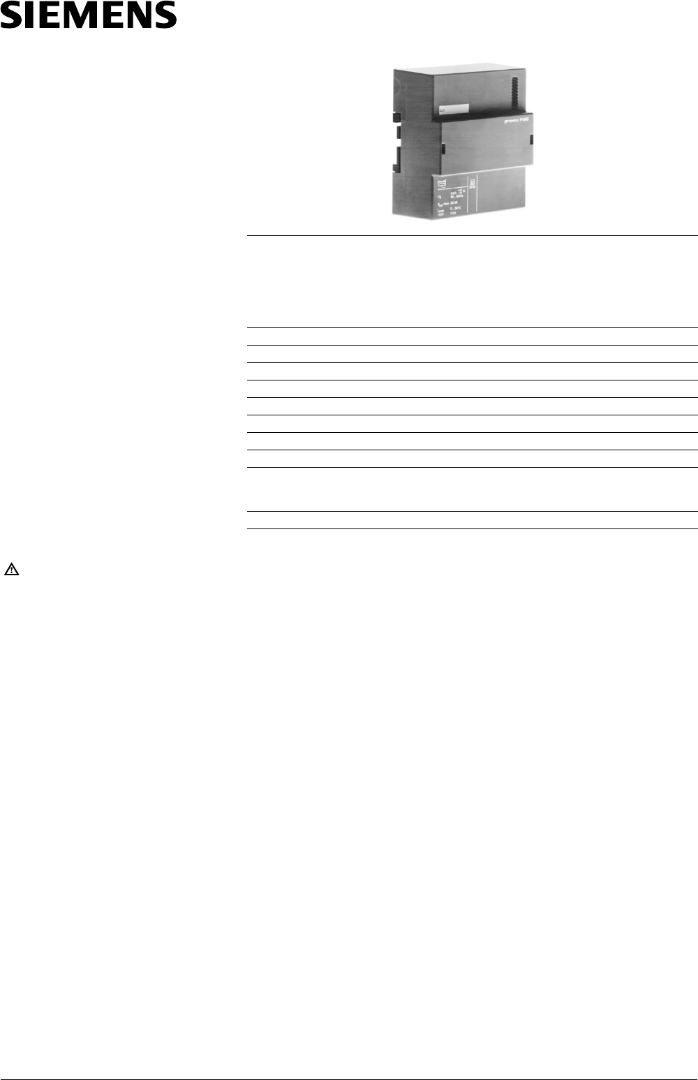
PVM9
Signal converter /
power amplifier 32 W
The PVM9 proportional signal
converter / power amplifier is used
to drive magnetic valves from a
DC 0 ...10 V or DC 0 ... 20 V phase cut
control signal.
Warning
• Controller and power amplifier
PVM9 must be supplied from the
same phase
• Where the DC 0 ...10 V signal is
derived from controllers, an
isolated AC 24 V supply from a se-
parate transformer must be
provided
• Switch off electricity supply before
removing the power amplifier or
plugging it into the baseplate
• Do not touch the PCB. Electronic
components can be damaged by
electrostatic discharge.
PVM9
Technical data
Power supply Extra low voltage (SELV, PELV)
Supply voltage AC 24 V, 50 ... 60 Hz
– Max. tolerance +15 /–10 %
Controller fuse T 2 A (slow blow)
Controller consumption max. 3 VA
Control voltage DC 0 ...10 V or DC 0 ... 20 V phase cut
Output voltage DC 0 ... 20 V phase cut
Output power 32 W max.
Connection terminals Screw terminals for max. 2.5 mm
2
wire
Protection class II ( 1 )
Protection standard IP30 to IEC529
Ambient temperature
Operation 0 ... 50 °C
Storage – 25 ... 50 °C
Weight (incl. packaging) 0.66 kg
Principle of operation
The PVM9 functions as a signal converter and / or power amplifier to give
a phase cut output rated at 32 W (max.). There is provision for two alterna-
tive signal inputs:
– DC 0 ...10 V for the control of magnetic valves which can only accept a
phase cut signal
or
– DC 0 ... 20 V phase cut, for use when the total power required by the
valve(s) exceeds the power rating of a controller having a phase cut
output.
Construction, mounting and dimensions
See data sheet 5559
5
181