
User Manual

16/18
Siemens Building Technologies VISONIK Building Process Station BPS / NetBPS CM2N8305de
Landis & Staefa Division 20.06.00
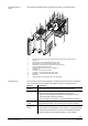
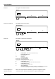
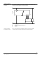
Geräteschaltpläne
Grundgerät ohne P-Bus-Anschluss:
G
G0 PD PU PC
II IIII
AC 24 V
8305G01
PRV2.00
Tool
X
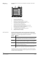
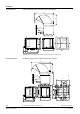
Grundgeräte mit P-Bus-Anschluss:
GG0
II IIII
AC 24 V
8305G02
PRV2.32/PRV2.64
Tool
X
P-Bus
PD PU PC
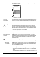
Grundgerät mit zwei P-Bus-Anschlüssen:
G
G0 PD2 PU2 PC2
II IIII
AC 24 V
8305G03
PRV2.128
Tool
X
P-Bus 2
PD1 PU1 PC1
P-Bus 1
I Klemmenblock I: PRX1.1P (PVX1.2P für PRV2.128)
Betriebsspannung AC 24 V:
G Systempotential
G0 Systemnull
P-Bus (Prozess-Bus):
PC, PC1, PC2 Synchronisationsleitung
PD, PD1, PD2 Datenleitung bidirektional
PU, PU1, PU2 Bezugsspannung DC 23 V (gegen G0)
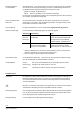
II Klemmenblock II (Option)
für Kommunikationseinschübe COM 2 oder weitere Einschübe
III Klemmenblock III (Option)
für Kommunikationseinschübe COM 1
X Tool-Steckanschluss
frontseitig, mit Schnittstelle V.24/V.28 für Tool-PC (via Tool-Adapter) und Schnittstellen
RS-485 für BLN (Building Level Network) und FLN (Floor Level Network)
Siehe in den entsprechenden Datenblättern gemäss den Angaben im Kapitel
"Technische Daten", Abschnitt "Schnittstellen der optionalen Einschübe".
PRV2.00
PRV2.32 und PRV2.64
PRV2.128
Geräteschaltpläne für
optionale Einschübe