
User Manual
9/18
Siemens Building Technologies VISONIK Building Process Station BPS / NetBPS CM2N8305en
Landis & Staefa Division 05.10.2000
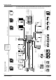
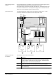
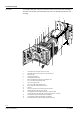
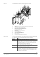
The following picture shows the mechanical structure from the rear:
1
5
12
8411Z02
7
8
9
10
11
2
3
4
6
1 Terminal block PRX1.1P (PVX1.2P for PRV2.128) for power supply, terminal slot I
2 Housing
3 Terminal slot II for COM2 communication cards
4 Terminal slot III for COM1 communication cards
5 Break-off recesses for connecting plug and displays
for COM1 communication cards
6 Power supply with P-bus connection, slot "A"
7 Electronics unit
8 Slot "G" for program cards
9 Slot "C" for COM2 communication cards
10 Slot "I" for COM1 communication cards
11 Battery compartment
12 Main circuit board with plug connections for the cards
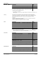
The unit has been designed for control cabinet front panel mounting or wall mounting in
the cabinet by means of an additional base plate. Elements and features:
Element Feature
Housing Plastic housing with standard dimensions as per DIN 43 700.
Electronics unit Plug-in unit. Two screws in the corners for attaching it to the housing
and sealing facility to prevent unauthorised removal. Components:
− Operating and display front. Cover can be opened with key only.
− Main circuit board and power supply insert.
− Three slots for program and communication cards.
Label Neutral label on compartment. Exchangeable against a system family
label. The labels are part of the accessories.
Terminal blocks Snap-on facility at the rear wall of the housing on three predefined
terminal slots: Terminal block I for power supply and P-bus, terminal
block II and III for communication cards. The terminal blocks can be
turned by 180° for wall mounting.
Rear view
Basic concept