
User Manual
8/18
Siemens Building Technologies VISONIK Building Process Station BPS / NetBPS CM2N8305en
Landis & Staefa Division 05.10.2000
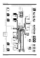
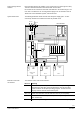
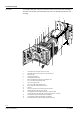
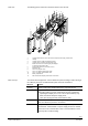
Mechanical design
The following illustration shows the mechanical structure of the basic unit consisting of
electronics unit, housing, and terminal block as well as an optional base plate for wall
mounting:
8411Z01
14
17
1
3
5
6
7
8
9
12
13
15
16
10
11
2
4
1 Transparent front cover with slots for cover card
2 Removable insert for tool connection on closed front cover
3 Electronics unit
4 Swing-out compartment
5 Exchangeable system label
6 Battery compartment for batteries of type Mignon 1.5 V
7 Slot "I" for COM1 communication cards
8 Slot "G" for program cards
9 Slot "C" for COM2 communication cards
10 Power supply with P-bus connection, slot "A"
11 Housing
12 Recess for side plugs on the COM1 communication card
13 Mounting bracket for housing, top or bottom
14 Terminal block for power supply, terminal slot I, snap-on holders
(Terminal blocks are turned by 180° on flush panel mounting = ex-factory)
15 Terminal slot for COM1 communication card (optional)
16 Terminal slot for COM2 communication card (optional)
17 Base plate PRM1.1W for wall mounting (separate accessory)
Front view