
User Manual
7/18
Siemens Building Technologies VISONIK Building Process Station BPS / NetBPS CM2N8305en
Landis & Staefa Division 05.10.2000
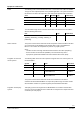
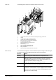
Data exchange with the I/O modules occurs via the three-core P-bus (process bus).
This bus is described in detail in data sheet 8022 "Process Bus".
I/O modules on the same P-bus have their own address in the number range of 1 to
max. 255. The addresses are set using address plugs in the I/O modules. Refer to
"Basic Data of the I/O Module System", data sheet 8102.
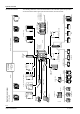
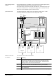
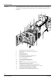
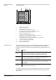
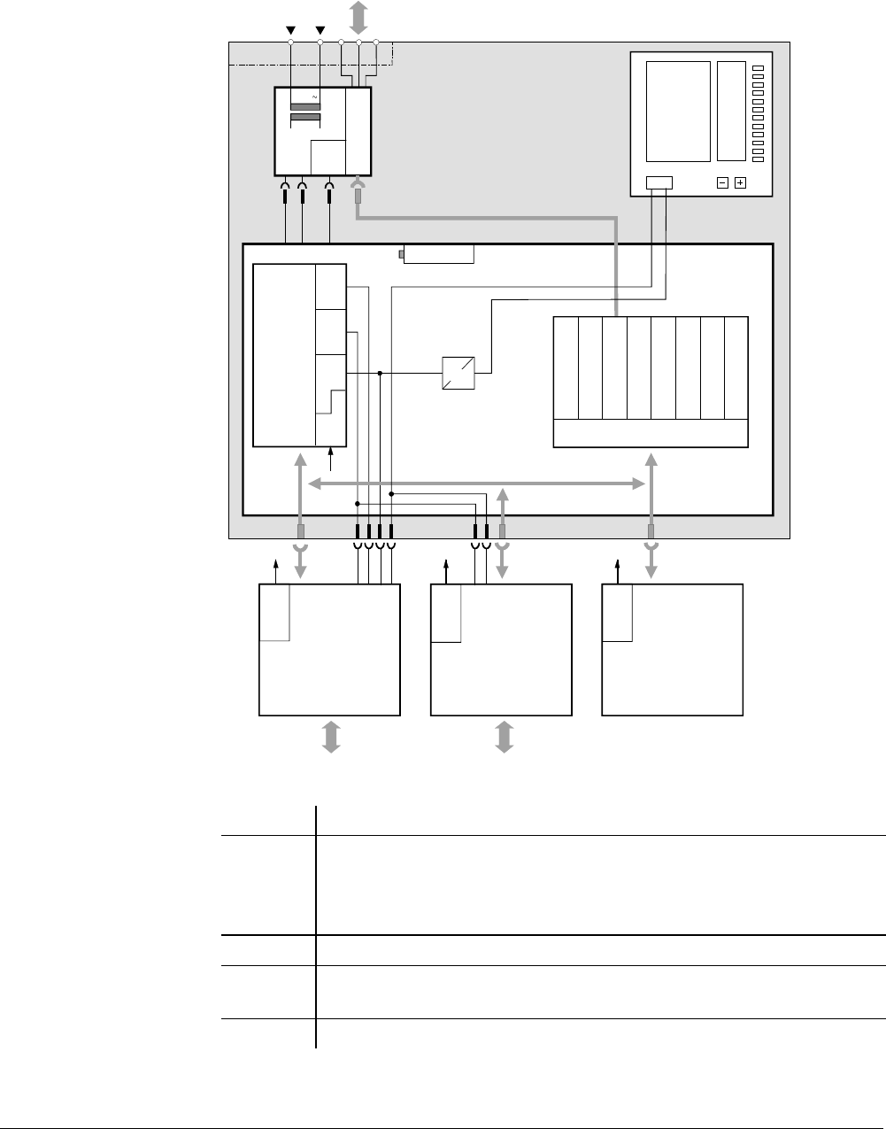
The following illustration shows the basic unit with power supply (here: 1 P-bus
connection) and main circuit board as well as the possible cards:
24 V
SCC
2
SCC
1
SCC
3
ID
LCD
Tool
V.28
ID
EEPROM
ID
EEPROM
ID
EEPROM
AC 24 V
G G0 PD PU PC
SCP
BPS1.C1/1E
PVC1...
PVC2... PVA3...
8305B01en
PRG1... power supply
ASIC
Battery 1.5 V
Main circuit board
Basic unit PRV2...
Voltage supervision
P-bus control
Frequency
transmitter
Real-time clock
Page recognition
I/O connections
EEPROM
Communication
card
COM1
Operating
cards
Program
card
PRX1.1P terminal block
Operator front
Mc
68302
Addresses / Data
P-bus driver
P-bus
Power
slide
µ
P supervision
Communication
card
COM2
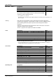
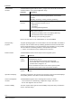
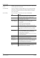
The elements on the main circuit board are:
Element Meaning
MC68302 16/32 bit microprocessor (16 data lines, 32 bit internal processing) with
integrated SCC and SPC communication blocks. Runs the operating
system software and the plant operating programs. Controls the LCD
displays and the external communication ports.
SCC 1..3 Serial communication controller with direct memory access (DMA).
SCP Serial SPC communication port. This port also helps identify the cards and
their versions (ID).
ASIC Application-Specific Integrated Circuit: Checks and controls the periphery.
Data exchange with I/O
modules
System architecture
Elements of the main
circuit board