
User Manual
16/18
Siemens Building Technologies VISONIK Building Process Station BPS / NetBPS CM2N8305en
Landis & Staefa Division 05.10.2000
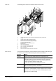
Internal diagrams
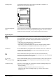
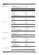
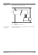
Basic unit without P-bus connection:
G
G0 PD PU PC
II IIII
AC 24 V
8305G01
PRV2.00
Tool
X
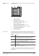
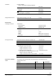
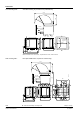
Basic units with P-bus connection:
GG0
II IIII
AC 24 V
8305G02
PRV2.32/PRV2.64
Tool
X
P-Bus
PD PU PC
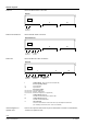
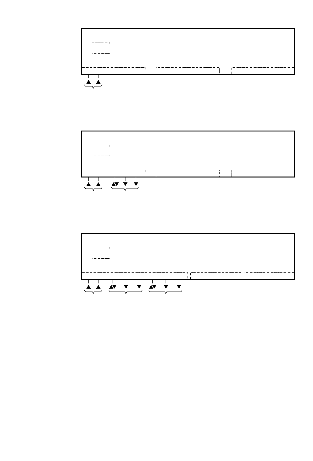
Basic unit with two P-bus connections:
G
G0 PD2 PU2 PC2
II IIII
AC 24 V
8305G03
PRV2.128
Tool
X
P-Bus 2
PD1 PU1 PC1
P-Bus 1
I Terminal block I: PRX1.1P (PVX1.2P for PRV2.128)
AC 24 V operating voltage:
G System potential
G0 System neutral
Process bus (P-bus):
PC, PC1, PC2 Synchronisation line
PD, PD1, PD2 Data line, bi-directional
PU, PU1, PU2 Reference voltage DC 23 V (against G0)
II Terminal block II (optional)
for COM2 communication cards or further cards
III Terminal block III (optional)
for COM1 communication cards
X Tool connection
on the front, with interface V.24/V.28 for tool PC (via tool adapter and interfaces
(RS = Building Level Network, FLN = Floor Level Network)
Refer to the respective data sheets as per the information in sections "Technical data",
"Interfaces for optional cards".
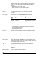
PRV2.00
PRV2.32 and PRV2.64
PRV2.128:
Internal diagrams for
optional cards