
Installation Instructions
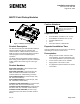
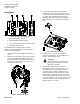
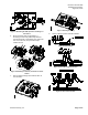
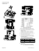
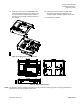
Table Of Contents
- Figure 1. MS/TP Point Pickup Module.
- Product Description
- Product Numbers
- Caution Notations
- Expected Installation Time
- Prerequisites
- Installation
- Figure 2. Back plate knockout holes.
- Figure 3. Removing the cover
- Figure 4. Removing the PCB.
- Figure 7. Routing I/O wiring.
- Figure 8. Power Wiring.
- Figure 9. FLN 2 wire network interface.
- Figure 10. FLN 3-wire interface.
- Figure 11. Wiring I/O to terminals.
- Figure 12. 6 Point Digital controller board.
- Figure 13. 6 Point Analog controller board
- (PPM-2U3322.BPF and PPM-2U3322.BPR)
- (PPM-3U63.BPR, for China only)
- Figure 14. 12 Point Combination controller board.
- Table 1. DIP Switch Settings for Baud Rate.
- Figure 15. Installing front cover to back plate.
- Figure 16. MSTP PPM Dimensions.
- I/O Configuration Diagrams
- Figure 17. AI/DI wiring for 6 point digital.
- Figure 18. DO wiring for wiring for 6 point digital.
- Figure 19. Analog input wiring.
- Figure 20. Universal input wiring.
- Figure 21. Analog output wiring.

Document No. 550-992
Installation Instructions
August 20, 2014
Page 2 of 6 Siemens Industry, Inc.
Installation
Figure 2. Back plate knockout holes.
1. Bottom plate wiring access
2. 100 mm electrical box mounting
3. 4” x 4” electrical box or flat surface mounting
4. Side plate wiring access
The back plate has knockout holes in various
positions, as well as DIN clips, to accommodate a
variety of mounting options.
1. Confirm that the power supply to the device is
OFF.
2. Remove the cover by first removing the bottom
screws (1). While gently pulling on the cover,
insert the flat blade of the small screwdriver into
the pocket of each snap-tab at the top of the
unit and pry to unlock (2).
Figure 3. Removing the cover
3. Remove the printed circuit board (PCB) by
removing the screw attaching the PCB to the
housing. Once the screw is removed, gently lift
the lower edge of the board (closest to the
screw) up and slide downward, to disengage
the top portion of the PCB from the retaining
clips.
Figure 4. Removing the PCB.
4. Using the pliers, remove the knockouts as
required for mounting to an electrical box or a
surface, and reattach the PCB.
CAUTION:
Failure to remove the PCB before
removing the knockouts can result in
damage to the PCB!
5. The DIN clips should first be removed if
mounting the device to a flat surface, or to an
electrical box that is flush with the wall. To
remove the clips, insert the flat blade of the
small screwdriver into the pocket of the clip’s
snap-tab and gently lift the tab up so it clears
the wire spring, then slide the clip to the center
of the unit (1). Once in the center, grab the end
of the clip and lift it up (2). This allows you to
slide the clip out of its track.