
User Manual
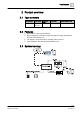


Product overview
Mechanical design
2
6 | 29
Siemens Industry, Inc.
A6V10958126_en
--
_a
Building Technologies
2017
-
06
-
30
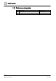
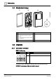
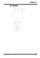
2.4 Mechanical design
1 Gasket for panel mounting 4 KNX PL-Link bus connector
2 Base plate with:
● screw holes for all common conduit
boxes
● gaining channels for wiring from center,
up, or bottom
5 Jack connector for tool connection
3 Room operator unit
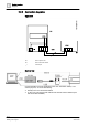
2.5 Diagrams
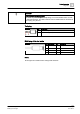
2.5.1 Connection terminals
KNX PL-Link plug
Connector Pin Description
+ KNX PL-Link (positive)
- KNX PL-Link (negative)
To find the location of the KNX PL-Link plug, refer to the
Mechanical design
.
NOTICE! You can choose either pair of pins to connect.