Room operating unit for Flexit POS8.
Table of Contents 1 1.1 1.2 1.3 About this document ............................................................................. 3 Revision history ...........................................................................................3 Before you start ...........................................................................................3 Reference documents..................................................................................4 2 2.1 2.2 2.3 2.4 2.5 2.6 Product overview ...........
About this document Revision history 1 1 About this document 1.1 Revision history Revision Date Changes Section a Sep. 2016 First edition All 1.2 Before you start Trademarks The table below lists the third-party trademarks used in this document and their legal owners. The use of trademarks is subject to international and domestic provisions of the law. Trademarks Legal owner KNX® KNX Association, B - 1831 Brussels-Diegem Belgium http://www.knx.
1 About this document Reference documents 1.3 Reference documents Ref. Document title Document number [1] Data sheet A6V10733771 [2] Mounting instructions A6V10733764 4 | 29 Siemens Industry, Inc.
Product overview Type summary 2 2 Product overview 2.1 Type summary Product number Stock number Temperature sensor POS8.4420/414 S55625H422-A414 Yes LCD display Minimal quantity of order Yes 20 2.2 Features ● ● ● ● Measurement of the room temperature Keys for adjustment of the room temperature setpoint, supply air/exhaust air fan control, time settings, etc. LCD display of room temperature, operating modes, and time. 2-wire interface to the controller through KNX PL-Link 2.
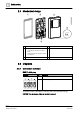
2 Product overview Mechanical design 2.4 Mechanical design 1 Gasket for panel mounting 4 KNX PL-Link bus connector 2 Base plate with: 5 Jack connector for tool connection 3 ● screw holes for all common conduit boxes ● gaining channels for wiring from center, up, or bottom Room operator unit 2.5 Diagrams 2.5.
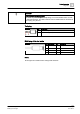
Product overview Diagrams 2 NOTICE Wires are NOT interchangeable! The device is protected against faulty wiring, but communications does not work on interchanged wires. The KNX / KNX PL-Link bus MUST NOT be connected to the tool plug, only the tool. Tool plug Connector Pin Description + KNX PL-Link (positive) - KNX PL-Link (negative) RJ45 plug of the tool cable Connector Pin Description Pin Description 1 CE+, KNX 5 Voltage 16V 2 CE-, KNX 6 N.C. 3 N.C. 7 Ident'pin 4 N.C.
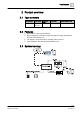
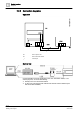
2 Product overview Diagrams 2.5.2 Connection diagrams Operation R1 Room operator unit N1 Room automation station Twisted pair Service tool Connect the ABT to load the application in the room automation station, or for service purposes, do one of the following: ● Directly to the room automation station ● To the room unit using the tool cable and the OCI702 service interface (see data sheet A6V10438951) 8 | 29 Siemens Industry, Inc.
Product overview Dimensions 2 2.6 Dimensions Siemens Industry, Inc.
3 Important information on safety and disposal General regulations 3 Important information on safety and disposal This section explains general and system-specific regulations for mains and operating voltages. It includes important information for your safety and the safety of the entire plant. 3.1 General regulations Please comply with the following general regulations during engineering and execution: ● Electrical and mains power ordinances for the given country.
Important information on safety and disposal Disposal 3 3.4 Disposal The device is considered an electronics device for disposal in terms of European Directive 2012/19/EU and may not be disposed of as domestic garbage. ● Dispose of the device through channels provided for this purpose. ● Comply with all local and currently applicable laws and regulations. Siemens Industry, Inc.
4 Mounting and installation Preparation 4 Mounting and installation Comply with the following notes, as well as the Mounting instructions (A6V10733764) to mount the room operation unit. 4.1 Preparation Check package contents Check the package content for visible signs of transport damage and for completeness. Do not install parts damaged during shipment. Contact your Siemens representative in the event of damaged parts.
Mounting and installation Mounting instructions 4 4.2 Mounting instructions Mounting instructions ● Mounting instructions (A6V10733764) are enclosed with the devices. ● Remove the breakout on the housing before putting the cable into the gaining channel. If 4-wire cables are used for daisy chain wiring, remove the cable coating, as it will not fit in the gaining channel.
4 Mounting and installation Mounting instructions Dismounting/service 14 | 29 Siemens Industry, Inc.
Commissioning Programming pin and service LED 5 5 Commissioning Prerequisites Before commissioning a room operator unit, ensure that an application is downloaded on to the connected room automation station, from where the functions are downloaded to the room operator unit.
5 Commissioning Programming pin and service LED - If the test is positive, the LED is lit continuously. - If the test fails, the LED flashes (1 s on, 1 s off). 2. Briefly press the programming pin (<0.5 s) to stop displaying the result of the connection test. The service LED goes off. 5.1.3 Reset to factory setting Press the programming pin (>20 s). The device is locked and reboots within 8 seconds. The room automation station removes it from its device list.
Technical data 6 6 Technical data Power supply* Operating voltage KNX/PL-Link DC 21...30V Max power consumption 7...10 mA Interfaces Type of port between room automation station and room operator unit KNX/ PLLink Baud rate 9.6 kbps Protocol KNX PL-LINK Standard KNX plug Wire diameter 0.8 mm, max. 1.
6 Technical data Standards, directives and approvals EU conformity (CE) A5W90002244 RCM conformity to EMC emission standard A5W90002245 CSA Compliance CSA C22.2M205 IC Compliance CAN ICE-3(B)/NMB-3(B) UL Compliance UL916, UL873/UL60730 FCC Compliance Part 15 of the FCC rules. Operation is subject to the following two conditions: 1) the device may not cause harmful interference, and 2) the device must accept any interference received, including interference that may cause undesired operation.
Functions 7 7 Functions Display example and element functions Elements Functions Indicates an operable element / Auto mode enabled/disabled Timer high mode Home mode/Away mode / Room temperature Supply air/Exhaust air / Electrical heater enabled/disabled / Timer mode / / Prolongation mode of Cooker hood mode/High mode/Fire place mode Alarm notification Alarm notification OK, but not acknowledged Alarm notification acknowledged Alarm notification, normal, acknowledged Service notification Servi
7 Functions Elements Functions General settings page Home page Fan speed settings page Supply air temperature settings page Alarm list is empty Read parameter mode 20 | 29 Siemens Industry, Inc.
Operation Home page 8 8 Operation 8.1 Home page In manual operation mode Button 1 Toggle between Home mode and Away mode Button 5 Enter the prolongation function settings page Button 2 and 6 No function (no arrow symbols displayed) Button 3 and 7 Toggle between HIGH (Comfort mode) and HOME (EcoComfort mode) Button 4 and 8 Toggle through different pages: Home, Fan Speed Settings, Supply Air Temperature Settings and General Settings.
8 Operation Fan speed settings page 8.2 Fan speed settings page Button 1 and 5 Toggle through different operation modes: Home, High, Fire (fire place), Cook (kitchen hood) and Away mode Button 2 and 6 Set supply air fan speed Button 3 and 7 Set exhaust air fan speed Button 4 and 8 Toggle through different pages: Home, Fan Speed Settings, Supply Air Temperature Settings and General Settings. 8.
Operation General settings page 8 In Away mode Button 1 and 5 Toggle between Home and Away mode Button 2 and 6 Set supply air temperature Button 3 and 7 Adjust the time delay setting; the timer starts to run when Away mode is activated Button 4 and 8 Toggle through different pages: Home, Fan Speed Settings, Supply Air Temperature Settings and General Settings. 8.
8 Operation Prolongation functions 8.
Operation Expert mode If the icon keeps displaying as 8 , you can manually acknowledge it by performing the following steps: 1. Press Button 4 and 8 for at least 3 seconds to enter the expert page. 2. Press Button 6 to acknowledge the service notification. If the service notification is OK, then the icon disappears on the screen. If the icon appears on the screen, then the service notification is acknowledged.
8 Operation Standby page If the alarm notification is acknowledged to be ok by the controller before you acknowledge it, then the icon becomes . In this case, you must acknowledge it on the device by performing the following steps: 1. Press Button 4 and 8 for at least 3 seconds to enter the expert page. 2. Press Button 6 to acknowledge the alarm notification. 8.
Appendix Parameters 9 9 Appendix 9.
9 Appendix Parameters P32 Input FIRE PLACE on/off P33 Input HOME/AWAY on/off P34 Input Air quality on/off P35 Input Humidity %rh 28 | 29 Siemens Industry, Inc.
Issued by Siemens Switzerland Ltd Building Technologies Division International Headquarters Gubelstrasse 22 CH-6301 Zug +41 41-724 24 24 www.siemens.com/buildingtechnologies Document ID: A6V10958126_en--_a Edition: 2017-06-30 © Siemens Switzerland Ltd, 2017 Technical specifications and availability subject to change without notice.