
User Manual


5
Siemens
A6V11946236_en--_a
Smart Infrastructure
2020-1-16
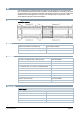
Status
Meaning
Red flashing at 2 Hz
BSP error or slave address error
Green on
BSP running
The status of BUS LED is defined as follows:
Status
Meaning
Red on
Communication error
Green on
Communication running
Orange on
Communication running but parameter not successfully
configured
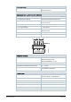
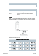
DIP switch
The extension module is equipped with DIP switch to communicate with the controller.
Switch 1, 2, 3, 4, and 5 are configurable to set the slave address, while switch 6 serves as
peripheral bus termination. If the extension module works as the termination in the network,
switch 6 must be set to ON.
The order of bit is from 5 to 1. The lowest bit is 5 while the highest bit is 1. Max. 31 slave
addresses can be configured as follows:
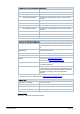
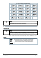
DIP Switch configuration of Extension Module
No.
Schematics
No.
Schematics
No.
Switch 5
No.
Schematics
1
9
17
25
2
10
18
26
3
11
19
27