
Installation Instructions


129-287
Operating Instructions
Rev. 1, October, 1999
Page 2 of 8 Siemens Industry, Inc.
Installation Conventions
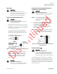
WARNING
Personal injury/loss of life may
occur if a procedure is not
performed as specified.
CAUTION
Equipment damage, or loss of
data may occur if the user
does not follow procedure as
specified.
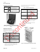
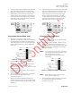
Figure 2. Actuator Commissioning Tool, Carrying
Case, Plug-in Transformer, and Three Extra Terminal
Blocks.
Application Overview
The Actuator Commissioning Tool has
four pushbutton selectable modes of operation as
follows:
Table 1. Output Control Signal Features.
Mode of
Operation
Description
Resistive *
0 to 135 ohms or 0 to 1k ohms for
use with resistive input actuators.
Voltage
0 to 20 Vdc for use with
proportional actuators
Current
0 to 20 mA for use with
proportional actuators
Floating Control
24 Vac (nominal) for use with
floating control and on/off
actuators
* The resistive mode is the default operating
mode when the commissioning tool is not
powered. To select other operating modes, the
ON/OFF switch must be turned ON. LEDs
indicate which mode is active.
The Commissioning Tool also provides additional
testing features as follows:
Table 2. Additional Testing Features.
Feature
Function
Power for Actuators
A 24 Vac (nominal) signal is
provided to power actuators that
are not externally powered.
Bias (for feedback
potentiometers)
A 5 Vdc bias signal is provided
through a 330 ohm resistor for
resistive feedback testing (for
feedback potentiometers).
Voltmeter
Measures 0 to 30 Vdc signal.
Switch Testing
LEDs display auxiliary contact
closure.
Use with dry contacts only!
The Commissioning Tool receives power by either:
• Applying 24 Vac (nominal) to the INPUTS
terminal block, or
• Connecting the 120V plug-in transformer
(provided) to its power jack.
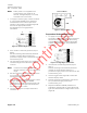
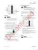
Dimensions
Figure 3. Commissioning Tool Dimensions (in./mm).