
Data Sheet for Product
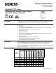
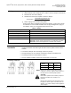


OpenAir
®
GPC Series, Spring Return, 35 lb-in, Rotary, Electronic Damper Actuators Technical Instructions
Document Number 155-782
February 26, 2019
Siemens Industry, Inc. Page 9
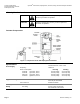
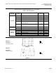
Start-Up/
Commissioning
GPC16x
Spring Return
Modulating Control
24 Vac/dc
1. Check Operation:
a. Connect wires 1 (red) and 2 (black) to the 24 Vac/dc power supply.
NOTE: With no input signal present, the GPC16x.1P Actuator with input signal
inversion switch set to Inverse Acting, will start driving towards 90°.
b. Use a Digital Multimeter (DDM) and set the dial to Vdc for the actuator input signal.
c. Connect wires 2 (black) and 8 (gray) to the DMM.
d. Apply to input signal wire 8 (gray):
Y = 10 Vdc (GPC16x.1P with input signal inversion switch set to Direct Acting).
Y = 0 Vdc (GPC16x.1P with input signal inversion switch set to Inverse Acting).
Allow the actuator shaft coupling to rotate from 0° to 90°.
e. Apply to input signal wire 8 (gray):
Y = 0 Vdc (GPC16x.1P with input signal inversion switch set to Direct Acting).
Y = 10 Vdc (GPC16x.1P) with input signal inversion switch set to Inverse Acting).
The shaft coupling returns to the 0 position.
2. Check Spring Return:
a. Set the DMM dial to Vdc.
b. Connect wires 2 (black) and 8 (gray) to the DMM.
c. Apply to input signal wire 8 (gray):
Y = 5 Vdc (GPC16x.1P).
Allow the actuator shaft coupling to rotate halfway.
d. Disconnect wire 1 (red).
The spring returns the actuator shaft coupling to the fail-safe "0" position.
e. Connect wire 1 (red) and the actuator moves.
3. Check Feedback:
a. Set the DMM dial to Vdc.
b. Attach wires 2 (black) and 9 (pink) to the DMM.
c. Apply the input signal as in Step 1d, to wire 8 (gray).
• The reading at the DMM should increase (decrease for GPC16x.1P with output
signal inversion switch set to Inverse Acting Feedback).
• The reading at the DMM should decrease (increase for GPC16x.1P with output
signal inversion switch set to Inverse Acting Feedback) and the actuator shaft
coupling returns to the fail-safe 0 position.
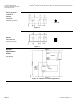
GPC12x
Spring Return
2-Position
24 Vac/dc
1. Check Operation:
a. Connect wires 1 (red) and 2 (black) to 24 Vac/dc power supply.
Allow the actuator shaft coupling to rotate from 0° to 90°.
b. Disconnect wire 1 (red) and the actuator shaft coupling returns to the "0" position.
2. Check Spring Return:
a. Connect wire 1 (red).
Allow the actuator shaft coupling to rotate halfway.
b. Disconnect wire 1 (red).
The spring returns the actuator shaft coupling to the fail-safe 0 position.