
Data Sheet for Product


OpenAir
®
GPC Series, Spring Return, 35 lb-in, Rotary Electronic Damper Actuators Technical Instructions
Document Number 155-782
February 26, 2019
Siemens Industry, Inc. Page 5
Sizing
The type of actuator required depends on several factors:
1. Obtain damper torque ratings (lb-in/ft
2
or Nm/m
2
) from the damper manufacturer.
2. Determine the area of the damper.
3. Calculate the total torque required to move the damper:
Total Torque =
SF
AreaDamper Rating Torque
1
4. Select a spring return actuator using Table 1.
1
Safety Factor: When calculating the total torque required, a safety factor should
be included for unaccountable variables such as slight misalignments, aging of
the damper, and so on. A suggested safety factor is 0.80.
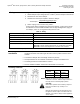
Table 2. Sizing.
Total Torque
Actuator
20 lb-in (2Nm)
GQD
> 20 lb-in < 35 lb-in (> 2 Nm < 4 Nm)
GPC
>35 lb-in 62 lb-in (>4 Nm 7 Nm)
GMA
>62 lb-in 160 lb-in (>7 Nm 18 Nm)
GCA
>160 lb-in 320 lb-in (>18 Nm 36 Nm)
Tandem GCA
ASK73.2U*: Tandem mounting bracket with any combination of GCA16x.
ASK73.1U*: Tandem mounting bracket for all other GCAx actuators.
*NOTE: Mechanically coupled actuators must be of the exact same type. Use the correct mounting bracket.
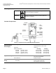
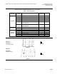
Mounting and
Installation
• The shaft adapter can be mounted on either side of the actuator. The actuator
mounting orientation and shaft length determine how they will be mounted on the
actuator.
• The minimum damper drive shaft length is 3/4-inch (20 mm).
• See Specifications for the minimum and maximum damper shaft dimensions.
• A mounting bracket is included with the actuator.
• See the detailed installation instructions included with each actuator.
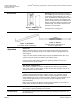
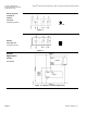
Auxiliary Switches
Switch
Switch
Makes
Switch
Breaks
A (fixed 5°)
< 5°
> 5°
B (fixed 85°)
> 85°
< 85°
NOTE: Both sets of contacts are open when actuator
is between 5° and 85°. Switches may be wired in a
Normally Closed or Normally Open position.
CAUTION:
Mixed switch operation to the switching outputs of
both dual end switches (5° and 85°) is not
permitted.
Either AC line voltage from the same phase must
be applied to all four outputs of the fixed dual end
switches, or UL-Class 2 voltage must be applied to
all four outputs.