
User Manual


7/8
Siemens 2-Port and 3-Port Zone Valves, PN 16 / 20 CE1N4867en
Building Technologies For Asia Pacific Use Only 02.10.2008
Actuators
Dimensions / Weight Dimensions and weight see «Dimensions»
Weight without auxiliary switch
with auxiliary switch
0.585 kg
0.692 kg
Base-plate die-cast aluminum Materials
Housing PBT
Union nut brass, nickel plated mat
Housing colors Base and cover light gray, RAL7035
Lever pigeon blue, RAL5014
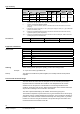
Auxiliary switch ASC2.1/18 Switch type changeover contact
Switching point at approx. 50 % stroke
Switching capacity AC 250 V (3 A resistive, 2 A inductive)
Connecting cable 3-core, 1.8 m / AWG18 (0.96 mm
2
)
1)
Phase cut and pulse-duration-modulated (PDM) signals are not suitable.
2)
Consider controller’s output power
3)
Standard is only met when the actuator is connected with a suitable cable conduit.
General ambient conditions
Operation
EN 60721-3-3
Transport
EN 60721-3-2
Storage
EN 60721-3-2
Environmental conditions Class 3K3 Class 2K3 Class 2K3
Temperature 1...50 °C -25...70 °C -5...50 °C
Humidity 5...85 % r. h. < 95 % r. h. 5...95 % r. h.
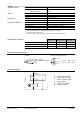
Connecting cable and terminals
Actuator Auxiliary switch ASC2.1/18
b
l
u
e
N
b
r
o
w
n
L
4867Z06
y
e
l
l
o
w
/
g
r
e
e
n
System neutral
System potential AC 230 V
Earth
Q14
Q11
Q12
4867Z07
b
l
a
c
k
/
p
i
n
k
b
l
a
c
k
/
b
l
u
e
b
l
a
c
k
/
r
e
d
0...50 %: Q11 → Q12
50 %...1: Q11 → Q14
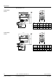
Connection diagram
L
N
Y
L
N
N
Y1 / Y11
N
L
(AC 230 V)
Q1
external
4867A01
N Controller (thermostat)
Y Actuator with zone valve
L System potential AC 230 V
N System neutral
Y1 Control signal OPEN
Q1 Controller contact