
User Manual


3/8
Siemens 2-Port and 3-Port Zone Valves, PN 16 / 20 CE1N4867en
Building Technologies For Asia Pacific Use Only 02.10.2008
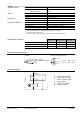
Accessories
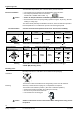
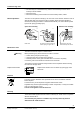
The optional auxiliary switch can be fitted to the actuator
with two screws.
It switches at a stroke of approx. 50 %.
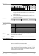
0…50 % : Q11 Q12 closed Q11 Q14 open
50 %…1 : Q11 Q12 open Q11 Q14 closed
4
8
6
7
Z
0
1
See «Technical data» for further information on the auxiliary switch.
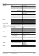
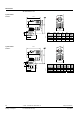
Sizing
2.77
2.22
0.27
0.55
0.83
1.11
0.22
0.17
1.67
0.11
0.083
0.055
0.027
10
40
60
80
100
200
300
400
600
p
v100
[kPa]
1
V
100
[m
3
/h]
p
v100
[bar]
1.0
0.1
0.01
0.02
0.06
0.2
0.6
2
6
3
V
100
[l/s]
0.1
0.2
0.4
0.3
1.0
0.8
0.6
10
8
6
4
3
2
20
0.04
0.4
4
5.55
p
max
2
1
2
3
4
6
8
k
v
s
5.
0
2.
0
3.
5
2
5
1
5
2
0
D
N
4867D01
p
v
100
= Differential pressure across the fully opened valve and the valve's control path A AB (2-
port valves), AB A (3-port diverting valves) by a volume flow
100
V
V
100
= Volume flow through the fully open valve (H
100
)
p
max = Maximum permissible differential pressure across the valve's control path, valid for the
entire actuating range of the motorised valve
100 kPa = 1 bar 10 mWC
1 m
3
/h = 0.278 l/s water at 20 °C
Example:
1
100
= 0.27 l/s
V
2 p
v
100
= 9 kPa
3 k
vs
value required = 3.5 m
3
/h
ASC2.1/18
auxiliary switch