
Data Sheet for Product

Technical Instructions MXG461B Series Modulating Control Valve
Document Number 125-4461 with Magnetic Actuator
October 23, 2018
Page 8 Siemens Industry, Inc.
Specifications,
Continued
Pipe connections
Screwed fittings Bronze/brass
Electrical connections
Cable entries 2 × Ø 20.5 mm (for M20)
Connection terminals Screw terminals for up to 12 AWG wires
Min. cross-sectional area
1)
0.75 mm
2
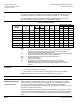
Max. cable length See Table 1, 9 (AWG)
Ambient conditions
Temperature
Operation
and storage 23°F to 113°F (-5°C to 45°C)
Transport -13°F to 158°F (-25°C to 70°C)
Humidity 5 to 95% rh (non-condensing)
Agency approvals
Degree of protection IP31 to EN60529
Conforms to CE requirements CA2T4461.1
UL 873
Certified to Canadian standard C22.2 No. 24
C-Tick N-474
PED 2014/68/EU
DVGW-Reg.-Nr. DW-6340BR0230
(EU potable water standard)
Miscellaneous
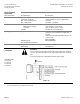
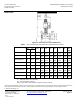
Weight See Figure 15
Dimensions See Figure 15
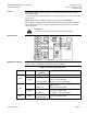
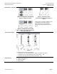
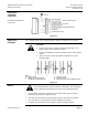
Connection
Terminals
WARNING:
If the controller and the valve receive their power supply from separate
sources, the valve transformer must not be grounded on the secondary
side.
A four-wire connection is mandatory with DC power supply.
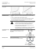
Controllers with:
0 to 10 Vdc
2 to 10 Vdc
0 to 20 mA
4 to 20 mA
Figure 12.
1. In case of strong vibrations, use high-flex stranded wires.