
Data Sheet for Product

MXG461B Series Modulating Control Valve Technical Instructions
with Magnetic Actuator Document Number 125-4461
October 23, 2018
Siemens Industry, Inc. Page 5
DIP Switches, Continued
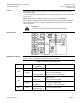
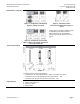
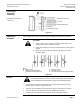
Figure 4. Assignment of Positioning
Signal Y: Voltage or Current.
.
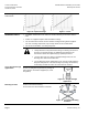
Figure 5. Selection of Valve
Characteristic: Equal-Percentage or
Linear.
Figure 6. Assignment of Correcting
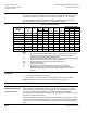
Span Y and U: 0 to 10 Vdc/0 to 20 mA or
2 to 10 Vdc/4 to 20 mA.
Output signal U (position feedback signal)
is dependent on the load resistance.
Above 500 ohm, it is automatically a
voltage signal; below 500 ohm a current
signal.
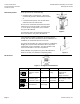
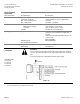
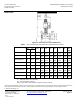
Forced Control Input
Transfer
Connections
Figure 7.
If terminal Z for the forced control input is:
− not connected, the valve will follow the Y-signal or the phase-cut signal.
− connected to G, the valve will fully open via control path A → AB.
− connected to G0, the valve will close via control path A → AB.
Signal Priority
1. Hand wheel position Man or Off
2. Forced control signal Z
3. Phase-cut signal
4. Signal input Y