
Data Sheet for Product

Technical Instructions MXG461B Series Modulating Control Valve
Document Number 125-4461 with Magnetic Actuator
October 23, 2018
Page 4 Siemens Industry, Inc.
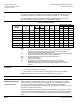
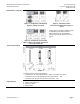
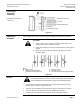
Manual Adjustment
Press (a) and turn the hand wheel (b):
• clockwise (CW). Control path A → AB can be
mechanically opened to between 80% and 90%,
or
• counterclockwise (CCW). The actuator will be
switched off and the valve closed.
As soon as the hand wheel is pressed and turned,
neither the forced control signal Z, the input signal
Y, nor the phase-cut signal acts on the actuator.
The green LED will flash.
For automatic control, the hand wheel must be set
to the Auto position. The green LED will be lit.
Figure 1.
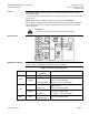
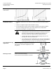
Calibration
If the electronics module is replaced or the actuator turned
through 180°, the valve’s electronics must be recalibrated. To
recalibrate, the hand wheel must be set to Auto.
The printed circuit board has a slot (see Figure 2). Calibrate by
bridging the contacts located behind the slot on the printed
circuit board, using a screwdriver. The valve will then travel
across the full stroke to store the end positions.
While calibration is in progress, the green LED will flash for
about 10 seconds (see Indication of Operating State).
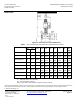
Figure 2.
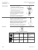
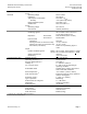
DIP Switches
Figure 3. Configuration DIP Switches.
DIP
Function
OFF (Default)
ON
Remarks
1
ON
OFF
Voltage or current
input
[ V ]
[ mA ]
Assignment of
terminal Y:
Voltage or current
2
ON
OFF
Correcting span
Terminals Y and U
0 to 10 Vdc,
0 to 20 mA
2 to 10 Vdc,
4 to 20 mA
Offset settings of input
and output
3
ON
OFF
Characteristic
V
log
(equal
percentage)
V
lin
(linear)
–