
Data Sheet for Product

Technical Instructions MXG461B Series Modulating Control Valve
Document Number 125-4461 with Magnetic Actuator
October 23, 2018
Page 2 Siemens Industry, Inc.
Application
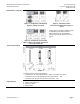
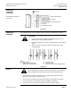
The MX4G61B Series valves are through-port or mixing valves with magnetic
actuators. The actuator is equipped with an electronics module for positioning control
and position feedback. If the power is off, the valve control path A → AB is closed.
The short positioning time, high resolution and high rangeability make these valves
ideal for modulating control of domestic, hot and cold-water systems.
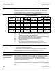
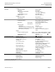
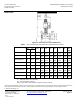
Table 1. Product Numbers.
Product
Number
Wire Gauge (AWG)
Line Size
Cv
p
s
p
max
S
NA
Pmed
I
N
16
14
12
(in)
(psi)
(psi)
(VA)
(W)
Fuse
L (ft)
MXG461B15-0.6
1/2
0.7
145
70
33
15
3.15
130
215
360
MXG461B15-1.5
1/2
1.8
145
70
33
15
3.15
130
215
360
MXG461B15-3
1/2
3.5
145
70
33
15
3.15
130
215
360
MXG461B20-5
3/4
5.8
116
70
33
15
3.15
130
215
360
MXG461B25-8
1
9.3
102
40
33
15
3.15
130
215
360
MXG461B32-12
1-1/4
14
87
40
43
20
4
100
165
260
MXG461B40-20
1-1/2
23
87
40
43
20
4
100
165
260
MXG461B50-30
2
35
87
40
65
22
6.3
65
100
185
Key:
p
max
= Maximum permissible differential pressure across the valve's control path,
valid for the entire actuating range of the motorized valve (maximum
recommended operating differential pressure).
p
s
= Maximum permissible differential pressure at which the motorized valve will
close securely against the pressure (close-off pressure).
S
NA
= Nominal apparent power for selecting the transformer.
Pmed = Average true power.
I
N
= Slow fuse (mandatory).
Cv = Nominal flow rate of cold water [41°F to 86°F (5°C to 30°C)].
L = Maximum cable length. With four-wire connections the maximum
permissible length of the separate 14 AWG Cu signal cable is 656 feet
(200 m).
Ordering
• The valve body and magnetic actuator assemblies cannot be separated.
• The brass/bronze fittings are included.
• When placing an order, specify the quantity, product number and description.
Example: 1 MXG461B15-0.6 valve and 1 ASE12 Replacement Circuit Board
Accessory
ASE12 Replacement Circuit Board
Technical/
Mechanical Design
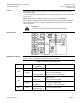
Operation Control
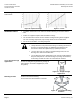
The electronics module converts the positioning signal to a phase-cut power signal,
which generates a magnetic field in the coil. This causes the armature to change its
position according to the interacting forces (magnetic field, counterspring, hydraulics,
etc.). The armature responds rapidly to any change in signal, transferring the
corresponding movement directly to the valve plug. This enables fast changes in load to
be corrected quickly and accurately.
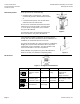
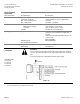
The valve’s position is measured continuously. Any disturbance in the system is rapidly
corrected by the internal positioning controller, which ensures that the positioning signal
and the valve stroke are exactly proportional, and also delivers the position feedback
signal.