
Data Sheet for Product

8/14
Siem ens Modulating control valves with magnetic actuators, PN 16 CE2N4461en
Building Technologies 2018-02-05
Technical data
Functional actuator data
Power supply
Extra low-voltage only (SELV, PELV)
AC 24 V Operating voltage AC 24 V °20% (SELV) or
AC 24 V class 2 (US)
Frequency 45...65 Hz
Typical power consumption P
med
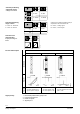
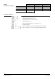
refer to table «Connection type», page 6
Standby < 1 W (valve closed)
Rated apparent power S
NA
refer to table «Connection type», page 6
Required fuse I
F
slow, refer to table «Connection type»
External supply line protection Fuse slow max. 10 A
or
Circuit breaker max. 13 A
Characteristic B, C, D according to
EN 60898
or
Power source with current limitation of
max. 10 A
DC 24 V
Operating voltage DC 20...30 V
Current draw at DC 24 V 0,5 A / 4 A (max.)
Input
Positioning signal Y DC 0/2...10 V or DC 0/4...20 mA
or Phase Cut signal Phs 0…20 V
Impedance DC 0/2...10 V 100 kς // 5nF (load < 0.1 mA)
DC 0/4...20 mA 240 ς // 5nF
Forced control Z
Impedance 22 kς
Close valve (Z connected to G0) < AC 1 V; < DC 0,8 V
Open valve (Z connected to G) > AC 6 V; > DC 5 V
No function (Z not wired) phase-cut- or positioning signal Y active
Output
Position feedback signal U Voltage DC 0/2…10 V; load resistance > 500 ς
Current DC 0/4...20 mA; load resistance ′ 500 ς
Stroke measurement
Nonlinearity
Inductive
± 3 % of end value
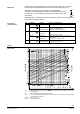
Positioning time
Positioning time < 2 s
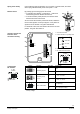
Electrical connections
Cable entries 2 x ⊕ 20,5 mm (for M20)
Connection terminals screw terminals for 4 mm
2
wires
Min. wire cross-section 0,75 mm
2
Max. cable length refer to «Connection type», page 6