
Data Sheet for Product

MXG461B Series Modulating Control Valve Technical Instructions
with Magnetic Actuator Document Number 125-4461
October 23, 2018
Siemens Industry, Inc. Page 9
Connection
Terminals,
Continued
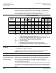
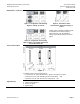
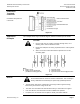
Controllers with phase-cut
0 to 20 Vdc
Figure 13.
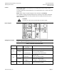
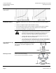
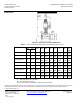
Application
Examples
This example shows only a schematic diagram, without installation-specific details.
CAUTION:
1. Use the valve only as a mixing or straight-through valve, not a
diverting valve. Note the direction of flow.
2. Ensure that adequate air venting is provided for the entire hydronic
system.
3. Select a non-return valve with minimum pressure loss for the
circulating pipes.
Key :
A Mixing circuit
B Mixing circuit with bypass
(underfloor heating system)
C Injection circuit
D Diverting circuit
E Injection circuit with throughport valve
Figure 14.
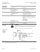
Service
In case of strong vibrations, use high-flex stranded wires.
CAUTION:
Do not disassemble the valve and actuator combination. This assembly is
factory-calibrated and should only be replaced by qualified personnel.
• The low-friction and robust, maintenance-free design makes regular servicing
unnecessary and ensures a long service life.
• The valve stem is sealed from external influences by a maintenance-free gland.
• If the red LED is lit, the electronics must be recalibrated or replaced.
• If required, the circuit board can be replaced. Order part number ASE12.