
Data Sheet for Product

MXG461B Series Modulating Control Valve Technical Instructions
with Magnetic Actuator Document Number 125-4461
October 23, 2018
Siemens Industry, Inc. Page 3
Control
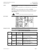
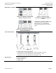
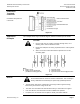
The magnetic actuator can be driven by any controller with a 0/2 to 10 Vdc or 0/4 to
20 mA output signal.
To achieve optimum control performance, it is recommended to use a 4-wire connection
for the valve.
NOTE: When using a dc power supply a 4-wire connection is mandatory.
The controller’s signal ground terminal M must be connected to the valve’s terminal M.
Terminals M and G0 have the same potential and are internally interconnected in the
valve’s electronics.
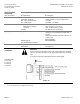
CAUTION:
You must use a four-wire connection with Vdc power supply.
Basic Diagram
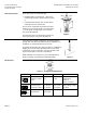
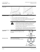
Spring Return Action
If the power or positioning signal is switched off or fails, the valve control path
(port A → AB) is automatically closed by the force of the spring.
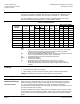
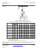
Table 2. Indication of Operating State.
LED
Indication
Operating State,
Function
Remarks, Troubleshooting
Green
Lit
Control mode
Normal operation; everything OK.
Flashing
Calibration
In manual control
Wait until calibration is finished
(green or red LED will be lit).
Hand wheel in Man or Off position.
Red
Lit
Calibration error
Internal error
Recalibrate (bridge contacts behind the
calibration slot).
Replace electronics module.
Flashing
Mains fault
DC Supply -/+
Check electric main network (outside the
frequency or voltage range);
Vdc supply +/- connection polarity.
Both
Dark
No power supply
Electronics faulty
Check electric main network, check wiring.
Replace electronics module.