
User Manual

13 / 20
Siemens Modulating refrigerant valves, PN 63 CE2N4717en
Smart Infrastructure 2019-11-25
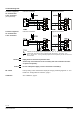
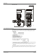
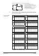
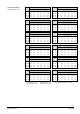
Dimensions
Dimensions in mm
2
1
0
m
in. 100
124
74
284
ø 22.4
ø 33.7
160
ø 60
4717
M01
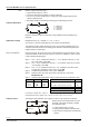
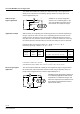
Valve sizing with correction factor
The applications and correction tables on the following pages are designed for help
with selecting the valves. To select the correct valve, the following data is required:
• Application
− Expansion (starting on page 14)
− Hot-gas (starting on page 16)
− Suction throttle (starting on page 18)
• Refrigerant type
• Evaporating temperature t
o
[ °C]
• Condensing temperature t
c
[ °C]
• Refrigeration capacity Q
0
[kW]
To calculate the nominal capacity, use the following formula:
• k
vs
[m³/h] = Q
0
[kW] / K…*
* K… for Expansion = KE
for hot-gas = KH
for suction throttle = KS
• The theoretical k
v
value for the nominal refrigeration capacity of the plant should not
be less than 50 % of the k
vs
value of the selected valve
• For accurate valve sizing, the valve selection program "Refrigeration VASP" is rec-
ommended
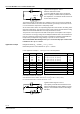
The application examples on the following pages deal with the principles only. They do
not include installation-specific details such as safety elements, refrigerant collectors,
etc.