s 4 717 ACVATIX™ Modulating refrigerant valves, PN 63 MVS661..N for ammonia (R717) and safety refrigerants • • • • • • • • • One valve type for expansion, hot-gas and suction throttle applications Hermetically sealed Selectable standard interface DC 0/2...10 V or DC 0/4...20 mA High resolution and control accuracy Precise positioning control and position feedback signal Short positioning time (< 1 second) Closed when deenergized Robust and maintenance-free DN 25 with kvs values from 0.10 to 6.
Type summary The refrigeration capacity refers to applications using ammonia. Product number DN kvs kvs reduced ∆pmax Q0 E Q0 H Q0 D SNA Pmed [m3/h] [m3/h] [MPa] [VA] [W] 22 12 MVS661.25-016N 25 0,16 0,10 [kW] 95 [kW] 10 [kW] 2 MVS661.25-0.4N 25 0,40 0,25 245 26 5 MVS661.25-1.0N 25 1,0 0,63 610 64 12 MVS661.25-2.5N 25 2,5 1,6 1530 159 29 MVS661.25-6.
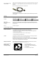
PTC conductive heating element ASR70 ASR70 extends the application range of valves for refrigerant temperatures at the valve inlet below 0° C. Typical applications pump systems with ammonia or CO2 refrigerant machines. Direct mounting on refrigerant valve, no adjustments. See data sheet A6V11858863. The PTC conductive heating element is supplied complete with Mounting Instructions A6V11858868. Ordering Valve body and magnetic actuator form one integral unit and cannot be separated.
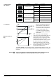
Switch Configuration of DIL switches Function ON ON / OFF Description ON Current [mA] OFF Voltage [V] 1) ON DC 2…10 V, 4…20 mA OFF DC 0…10 V, 0…20 mA 1) ON Current [mA] OFF Voltage [V] 1) ON 63 % OFF 100 % 1) Positioning signal Y 1 ON Positioning range Y and U 2 ON Position feedback U 3 ON Nominal flow rate kvs 4 1) Factory setting 4716D01en kvs-reduction Stroke Minimum stroke setting 100 % 80 % Y-input 0% 0% 100 % When kvs reduction (DIL switch 4 in position ON) the str
Forced control input ZC ZC – Function no function fully open closed G G function Transfer Connections G • ZC not connected • ZC connected to G • Valve will follow the Y-signal • Valve will fully open control path A AB • Minimum stroke set-ting with potentiometer Rv possible • ZC connected to G0 • Valve will close control path A AB Signal priority 1. Forced control signal ZC 2.
Connection type 1) The 4-wire connection should always be given preference! Product number 4-wire connection 3-wire connection SNA PMED STR PTR IF Wire cross-section [mm2] 1.5 2.5 4.0 2) max. cable length L [m] [VA] [W] [VA] [W] [A] MVS661..N 32 12 ≥50 ≥40 1.6…4 A 65 110 160 MVS661..N 32 12 ≥50 ≥40 1.
Engineering notes Depending on the application, it may be necessary to observe additional Installation Instructions and fit appropriate safety devices (e.g. pressurestats, full motor protection, etc.).
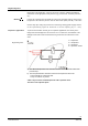
Mounting notes The valve should be mounted and commissioned by qualified staff. The same applies to the replacement electronics and the configuration of the controller (e.g. SAPHIR or PolyCool). 90° 4716Z16 90° • The refrigerant valves can be mounted in any orientation, but upright mounting is preferable. • Arrange the pipework in such a way that the valve is not located at a low point in the plant where oil can collect.
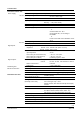
Technical data Functional actuator data Power supply Extra low-voltage only (SELV, PELV) AC 24 V Operating voltage AC 24 V ±20% (SELV) or AC 24 V class 2 (US) Frequency 45...65 Hz Typical power consumption Pmed 12 W Stand by < 1 W (valve closed) Rated apparent power SNA 32 VA (for selecting the transformer) Required fuse IF 1,6…4 A, slow External supply line protection Fuse slow max. 10 A or Circuit breaker max.
Materials Dimensions and weight Pipe connections Standards, directives and approvals Hysteresis Mode of operation Position when deenergized Mounting position 2) Valve body Seat / piston Sealing disk / O-rings Dimensions Weight Weld-on-ends / Solder connections typically 3 % modulating control path A AB closed Upright to horizontal steel / CrNi steel CrNi steel PTFE / CR (chloroprene) refer to "Dimensions", page 13 5.17 kg Referring to EN 1092-1 and ASME B16.25 schedule 40 Inner diameter 22.
General environmental conditions Operation EN 60721-3-3 Class 3K6 –25...55 °C 10...100 % r. h. Climatic conditions Temperature Humidity Transport EN 60721-3-2 Class 2K3 –25...70 °C < 95 % r. h. Storage EN 60721-3-1 Class 1K3 –5...45 °C 5...95 % r. h. Connection terminals Operating voltage AC / DC 24 V G G DC 0 ... 10 V / 2 ... 10 V 0 ... 20 mA / 4 ... 20 mA Control signal Measuring neutral (= G0) U DC 0 ... 10 V / 2 ... 10 V 0 ... 20 mA / 4 ...
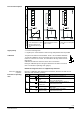
Connection diagrams Terminal assignment for controller with 4-wire connection (to be preferred!) Common Transformer G Terminal assignment for controller with 3-wire connection Separate Transformer G G U U Common Transformer G U Separate Transformer G G U U Indication of valve position (only if required). DC 0...10 V → 0...100 % volumetric flow V100 Twisted pairs. If the lines for AC 24 V power supply and the DC 0...10 V (DC 2...10 V, DC 0... 20 mA, DC 4...
Dimensions ø 60 160 4717M01 74 124 ø 22.4 ø 33.7 284 210 min. 100 Dimensions in mm Valve sizing with correction factor The applications and correction tables on the following pages are designed for help with selecting the valves.
Use of the MVS661..N as an expansion valve Note Observe engineering notes page 7 • Typical control range 20...100 %. • Increased capacity through better use of the evaporator • The use of 2 or more compressors or compressor stages significantly increases efficiency with low loads • Especially suitable for fluctuating condensing and evaporating pressures 40153A Capacity optimization 4 1 3 2 1 2 3 4 = = = = MVS661..
b) Refrigerant valve MVS661..N for capacity control of a chiller. • Typical control range 10...100 % • Energy-efficient operation with low loads • Allows wide adjustment of condensing and evaporating temperatures • Ideal for use with plate heat exchangers • Very high degree of frost protection + MVS661..N 4717Z08 Note A larger valve may be required for low-load operation than is needed for full load conditions.
Use of the MVS661..N as a hot-gas valve The control valve throttles the capacity of a compressor stage. The hot gas passes directly to the evaporator, thus permitting capacity control in the range from 100 % down to approximately 0 %. Indirect hot-gas bypass application 70179 + MVS661...N Suitable for use in large refrigeration systems in air conditioning plant, to prevent unacceptable temperature fluctuations between the compressor stages.
Correction table KH Hot-gas valve R717 tc \ to -40 -30 -20 R22 -10 0 10 tc \ to -40 -30 -10 0 20 19 14 00 8,9 8,4 6,3 20 38 38 38 38 35 19 20 15,3 15,1 14,8 14,6 13,2 6,5 40 67 66 65 64 64 63 40 24,2 23,7 23,2 22,8 22,4 22,1 60 110 107 105 103 102 100 60 35,7 34,7 33,8 33,0 32,3 31,7 10 tc \ to -40 -30 -20 38,1 30,5 00 60,9 59,8 58,1 47,1 20 87,3 84,9 82,5 80,2 -20 -10 R134a 0 10 76,1 tc \ to -40 00 4,5 -30 -20 -10 0
Use of the MVS661..N as a suction throttle valve 70177 + MVS661...N – Typical control range 50...100 %. Minimum stroke limit control: To ensure optimum cooling of the compressor, either a capacity controller must be provided for the compressor, or a minimum stroke must be set via the valve electronics. Bypass The minimum stroke can be limited to a maximum of 80 %. At zero load, the minimum stroke must be sufficient to ensure that the minimum gas velocity in the suction line is > 0.
Correction table KS Suction throttle valve tc R717 tc R22 ∆pv100 \ to -40 -30 -20 -10 0 10 ∆pv100 \ to -40 -30 -20 -10 0 10 0.15 / 20 2.7 3.7 4.8 6.0 7.3 8.8 0.15 / 20 1,2 1,5 1,9 2,4 2,9 3,4 0.15 / 50 2.3 3.2 4.2 5.2 6.4 7.8 0.15 / 50 0,9 1,2 1,5 1,9 2,3 2,7 0.45 / 20 3.2 5.2 7.4 9.7 12.1 14.8 0.45 / 20 1,5 2,3 3,0 3,9 4,8 5,7 0.45 / 50 2.8 4.6 6.5 8.5 10.7 13.1 0.45 / 50 1,2 1,8 2,4 3,0 3,8 4,6 tc R152A tc R134a ∆pv100 \ to -4
Revision numbers Product number Valid from rev. no. MVS661.25-016N A MVS661.25-0.4N A MVS661.25-1.0N A MVS661.25-2.5N A MVS661.25-6.3N A Issued by Siemens Switzerland Ltd Smart Infrastructure Global Headquarters Theilerstrasse 1a 6300 Zug Switzerland Tel. +41 58-724 24 24 www.siemens.com/buildingtechnologies © Siemens Switzerland Ltd, 2011 Technical specifications and availability subject to change without notice.