
User Manual

8 / 14
Siemens Modulating refrigerant valves, PN 63 A6V11160433en / A5W00038735
Building Technologies 2018-07-17
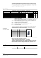
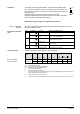
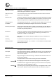
Connection terminals
G
Operating voltage AC / DC 24 V
U
G
DC 0 ... 10 V / 2 ... 10 V
0 ... 20 mA / 4 ... 20 mA
DC 0 ... 10 V / 2 ... 10 V
0 ... 20 mA / 4 ... 20 mA
Control signal
Measuring neutral (= G0)
Position feedback signal
Override input
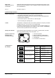
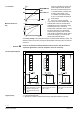
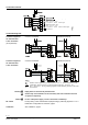
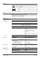
Connection diagrams
Common Transformer Separate Transformer
G
U
G
U
G
Common Transformer Separate Transformer
G
U
G
U
G
U
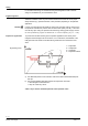
Indication of valve position (only if required). DC 0...10 V → 0...100 % volumetric flow V100
Twisted pairs. If the lines for AC 24 V power supply and the DC 0...10 V (DC 2...10 V,
DC 0... 20 mA, DC 4... 20 mA) positioning signal are routed separately, the AC 24 V line need
not be twisted.
Piping must be connected to potential earth!
Ground only one transformer on the secondary side if the controller and valve
are powered separately.
In case of DC power supply, a 4-wire connection is mandatory!
Factory setting: Valve characteristics equal-percentage, positioning signal DC 0...10 V.
Details see "Configuration DIL switches", page 3.
See "Calibration", page 5.
Terminal assignment
for controller with
4-wire connection
(to be preferred!)
Terminal assignment
for controller with
3-wire connection
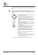
Warning
Caution
DIL switch
Calibration