
User Manual

5 / 14
Siemens Modulating refrigerant valves, PN 63 A6V11160433en / A5W00038735
Building Technologies 2018-07-17
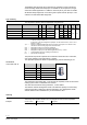
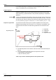
The printed circuit board of the MVS661..EX has a slot to facilitate calibra-
tion. To make the calibration, insert a screwdriver in the slot so that the con-
tacts inside are connected. As a result, the valve will first be fully closed and
then fully opened.
Calibration matches the electronics to the valve’s mechanism.
During the calibration process the green LED flashes for about 10 seconds;
refer to "Indication of operating state" (page 5).
01124
MVS661..EX refrigerant valves are supplied fully calibrated.
Execute a calibration after replacing the electronics, when the red LED is on or when
the valve is leaking (at seat).
LED Indication Function Remarks, troubleshooting
Green Lit Control mode Automatic operation; everything o.k.
Flashing Calibration in pro-
gress
Wait until calibration is finished
(green or red LED will be lit)
Red Lit Calibration error
Internal error
Recalibrate (operate button in opening 1x)
Replace electronics module
Flashing Mains fault Check mains network (outside the frequency or
voltage range)
Both Dark No power supply
Electronics faulty
Check mains network, check wiring
Replace electronics module
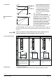
The 4-wire connection should always be given preference!
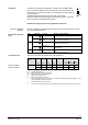
Product
number
S
NA
P
MED
S
TR
P
TR
I
F
Wire cross-section [mm
2
]
1,5 2,5 4,0
2)
[VA] [W] [VA] [W] [A] max. cable length L [m]
MVS661..EX 32 12 ″ 50 ″ 40 1,6…4 A 65 110 160
MVS661..EX 32 12 ″ 50 ″ 40 1,6…4 A 20 35 50
S
NA
= nominal apparent power
P
MED
= typical power consumption (Application)
S
TR
= Minimum transformer apparent power
P
TR
= Minimum DC supply power
I
F
= Minimum required slow-blow fuse
L = max. cable length; with 4-wire connections, the max. permissible length of the separate 1.5 mm
2
copper positioning signal wire is 200 m
1)
All information at AC 24 V or DC 24 V
2)
With 4 mm
2
electrical wiring reduce wiring cross-section for connection inside valve to 2.5 mm
2
.
Calibration
When is a calibration
required?
Indication of operating
state
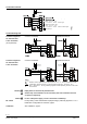
Connection type
1)
4-wire connection
3-wire connection