
User Manual

3 / 14
Siemens Modulating refrigerant valves, PN 63 A6V11160433en / A5W00038735
Building Technologies 2018-07-17
Should the valve’s electronics become faulty, the entire electronics housing is to be
replaced by spare part ASR61EX, which is supplied complete with Mounting Instruc-
tions (A5W00036611).
See table on page 14.
Technical design / functions
∂ 4 selectable standard signals for setpoint and measured value
∂ DIL switch to reduce the k
vs
value to 63 % of the nominal value
∂ Potentiometer for adjustment of minimum stroke for suction throttle applications
∂ Automatic stroke calibration
∂ Forced control input for "Valve closed" or "Valve fully open”
∂ LED for indicating the operating state
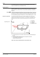
The MVS661..EX refrigerant valve can be driven by Siemens or third-party controllers
that deliver a DC 0/2...10 V or DC 0/4...20 mA output signal.
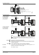
For optimum control performance, we recommend a 4-wire connection between con-
troller and valve. When operating on DC voltage, a 4-wire connection is mandatory!
The valve stroke is proportional to the control signal.
If the positioning signal is interrupted, or in the event of a power failure, the valve’s
return spring will automatically close control path 1 ⇓ 3.
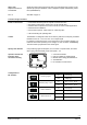
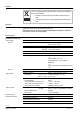
4716Z15
2
on
1234
G0GY UM ZC
1
3
4 5
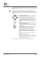
1 Connection terminals
2 LED for indication of operating state
3 Minimal stroke setting potentiometer Rv
4 Autocalibration
5 DIL switches for mode control
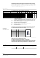
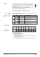
Switch Function ON / OFF Description
1
ON
Positioning signal Y
ON Current [mA]
OFF Voltage [V]
1)
2
ON
Positioning range Y and U
ON DC 2…10 V, 4…20 mA
OFF DC 0…10 V, 0…20 mA
1)
3
ON
Position feedback U
ON Current [mA]
OFF Voltage [V]
1)
4
ON
Nominal flow rate k
vs
ON 63 %
OFF 100 %
1)
1)
Factory setting
Spare parts
Replacement electron-
ics ASR61EX
Rev. no.
Features and benefits
Control
Spring return function
Operator controls and
indicators in the
electronics housing
Configuration of
DIL switches