
User Manual

10 / 14
Siemens Modulating refrigerant valves, PN 63 A6V11160433en / A5W00038735
Building Technologies 2018-07-17
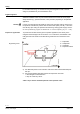
Disposal
The device is considered electrical and electronic equipment for disposal
in terms of the applicable European Directive and may not be disposed
of as domestic garbage.
∂ Dispose of the device through channels provided for this pur-
pose.
∂ Comply with all local and currently applicable laws and regula-
tions.
Warranty
Application-specific technical data must be observed.
If specified limits are not observed, Siemens Building Technologies / CPS Prod-
ucts will nor assume any responsibility.
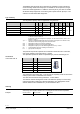
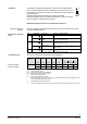
Technical data
Functional actuator data
Power supply
Extra low-voltage only (SELV, PELV)
AC 24 V
Operating voltage AC 24 V °20% (SELV) or
AC 24 V class 2 (US)
Frequency 45...65 Hz
Typical power consumption P
med
12 W
Stand by < 1 W (valve closed)
Rated apparent power S
NA
32 VA (for selecting the transformer)
Required fuse I
F
1.6…4 A, slow
External supply line protection Fuse slow max. 10 A
or
Circuit breaker max. 13 A
Characteristic B, C, D according to
EN 60898
or
Power source with current limitation of max.
10 A
DC 24 V
Operating voltage DC 20…30 V
Current draw 0,5 A / 2 A (max.)
Signal inputs
Positioning signal Y DC 0/2…10 V or DC 0/4…20 mA
Impedance DC 0/2…10 V 100 kς // 5nF (load < 0,1 mA)
DC 0/4…20 mA 240 ς // 5nF
Forced control ZC
Input impedance 22 kς
Close valve (ZC connected to G0) < AC 1 V; < DC 0,8 V
Open valve (ZC connected to G) > AC 6 V; > DC 5 V
No function (ZC not wired) Positioning signal Y active
Signal outputs
Position feedback U Voltage DC 0/2…10 V; load resistance ″ 500 ς
Current
DC 0/4…20 mA; load resistance
′
500
ς
Stroke measurement
Nonlinearity
Inductive
± 3 % of end value
Positioning
time Positioning time < 1 s
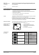
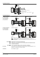
Electrical connection
Cable entry 3 x Ø 17 mm (for M16)
Minimal wire cross-section
Maximum wire cross-section
0.75 mm
2
2.5 mm
2
Tightening torque (terminal block) 0.5 – 0.6 Nm
1)