
Data Sheet for Product
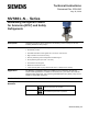

Technical Instructions MVS661..N Series Modulating Refrigerant Valves
Document Number 155-404 for Ammonia (R717) and Safety Refrigerants
May 11, 2016
Page 8 Siemens Industry, Inc.
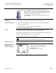
Installation Notes,
Continued
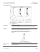
The flame should be large enough to ensure that the junction
heats up quickly and the valve does not get too hot.
The flame should be directed away from the valve.
During soldering, cool the valve with a wet cloth, for example,
to ensure that it does not become too hot.
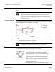
The valve is supplied complete with mounting instructions
(Document Number 74 319 0232 0).
Maintenance
The refrigerant valve is maintenance-free.
Repair
The electronics can be replaced by ordering the ASR61 Service Kit. If the valve’s interior is
subjected to extensive wear, the valve can be repaired by replacing the ASR.N valve
insert.
Warranty
Observe all application-specific technical data.
NOTE: If you ignore specified limits, Siemens Industry, Inc. will not assume any responsibility.
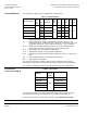
Specifications
Electrical
Power supply (extra low-voltage use only) (SELV, PELV)
24 Vac
Operating voltage 24 Vac ± 20%
Frequency 45 to 65 Hz
Typical power consumption
P
med
12W
Standby <1 W (valve fully closed)
Rated apparent power, S
NA
22 VA (for selecting the transformer)
Required fuse Slow, 1.6 to 4A
24 Vdc
Operating voltage 20 to 30 Vdc
Current draw 0.5A/2A (maximum)
Signal inputs
Control signal Y 0/2 to 10 Vdc, 0/4 to 20 mA
Impedance 0/2 to 10 Vdc 100K ohm/5nF (load <0.1 mA)
0/4 to 20 mA 240 ohm/5nF
Forced control ZC
Input impedance 22K ohm
Closing the valve (ZC connected to G0) <1 Vac; <0.8 Vdc
Opening the valve (ZC connected to G) >6 Vac; >5 Vdc
No function (ZC not wired) Positioning signal Y active
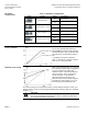
Signal outputs
Position feedback signal U Voltage 0/2 to 10 Vdc; load resistance > 500 Ω
Current 0/4 to 20 mA; load resistance < 500Ω
Stroke measurement Inductive
Non-linearity Accuracy +3% full scale
Positioning time
Less than 1 second
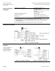
Electrical connections
Connection terminals Screw terminals for 12 AWG wire