
Data Sheet for Product

MVS661…N Modulating Refrigerant Valves Technical Instructions
for Ammonia (R717) and Safety Refrigerants Document Number 155-404
May 11, 2016
Siemens Industry, Inc. Page 19
MVS661…
as a suction throttle
valve
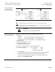
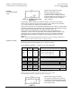
Figure 11. Suction Throttle Valve
Application.
Typical control range 50 to 100%.
Minimum stroke limit control:
To ensure optimum cooling of the
compressor, either a capacity controller
must be provided for the compressor, or a
minimum stroke must be set using the
valve electronics.
The minimum stroke is limited to a maximum of 80%. At zero load, the minimum
stroke must be sufficient to ensure that the minimum gas velocity in the suction line
is > 0.7 m/s and that the compressor is adequately cooled.
As the control valve closes, the evaporating temperature rises, and the air cooling effect
decreases continuously. The electronic control system provides demand-based cooling
without unwanted dehumidification and costly retreatment of the air.
The pressure at the compressor inlet falls and the power consumption of the
compressor is reduced. The energy savings to be anticipated with low loads can be
determined from the compressor selection chart (power consumption at minimum
permissible suction pressure). Compressor energy savings of up to 40% can be
achieved.
NOTE: The recommended differential pressure p
v100
across the fully open control valve is
between 2.2 psi (0.15 bar) < p
v100
< 7.25 psi (0.5 bar).
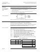
Application example
Refrigerant R134A; Q
0
= 9.5 kW; t
0
= 39°F (4°C); t
c
= 104°F (40°C);
Differential pressure across MVS661: p
v100
= 3.6 psi (0.25 bar)
In this application example, t
0
, t
c
and p
v100
are to be interpolated.
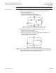
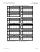
KS-R134a
t
0
= 32°F
(0°C)
t
0
= 50°F
(10°C)
Interpolation at
t
0
= 39°F
(4°C)
0.15/20
2.2
2.7
2.2 + [(2.7 – 2.2) × (4 - 0)/(10 - 0)]
2.4
0.15/50
1.7
2.1
1.7 + [(2.1 – 1.7) × (4 - 0)/(10 - 0)]
1.9
0.45/20
3.6
4.5
3.6 + [(4.5 – 3.6) × (4 - 0)/(10 - 0)]
4.0
0.45/50
2.7
3.4
2.7 + [(3.4 – 2.7) × (4 - 0)/(10 - 0)]
3.0
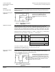
t
0
= 39°F
(4°C)
t
c
= 68°F
(20°C)
t
c
= 122°F
(50°C)
Interpolation at
t
c
= 104°F
(40°C)
p
v100
0.15
2.4
1.9
2.4 + [(1.9 – 2.4) × (40 - 20)/(50 - 20)]
2.1
p
v100
0.45
4.0
3.0
4.0 + [(3.0 – 4.0) × (40 - 20)/(50 - 20)]
3.3
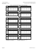
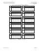
t
c
= 104°F
(40°C)
p
v100
2.2 psi
(0.15 bar)
p
v100
6.5 psi
(0.45 bar)
Interpolation at
p
v100
3.6 psi
(0.25 bar)
2.1
3.3
2.1 + [(3.3 – 2.1) × (0.25 – 0.15)/(0.45 – 0.15)]
2.5
k
vs
theoretical = 9.5 kW / 2.5 = 3.8 m
3
/h (CV = k
vs
× 1.156 = 3.8 × 1.156 = 4.4).
Valve MVL661.25-6.3 is suitable, since 3.8 m
3
/h / 6.3 m
3
/h x 10 % = 60% (> 50%).
It is recommended that the C
V
(k
vs
) value be set to 63% = 4.6 (4 m
3
/h).
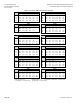
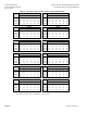
Figure 12.
Typical control range 10 to 100%.
The capacity controller ensures that the
compressor is adequately cooled, making
it unnecessary to set a minimum stroke in
the refrigerant valve.