
Data Sheet for Product


5 / 20
Siemens Modulating refrigerant valves, PN 63 CE2N4717en
Smart Infrastructure 2019-11-25
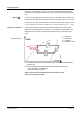
ZC
–
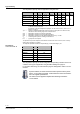
Function
no function fully open closed
Connections
G
G
G
Transferfunction
· ZC not connected
· Valve will follow the Y-signal
· Minimum stroke set-ting
with potentiometer Rv pos-
sible
· ZC connected to G
· Valve will fully open control
path A à AB
· ZC connected to G0
· Valve will close control path
A à AB
1. Forced control signal ZC
2. Signal input Y and/or minimum stroke set-ting with potentiometer Rv possible
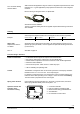
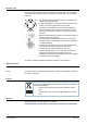
The printed circuit board of the MVS661..N has a slot to facilitate calibration.
To make the calibration, insert a screwdriver in the slot so that the contacts
inside are connected. As a result, the valve will first be fully closed and then
fully opened.
Calibration matches the electronics to the valve’s mechanism.
During the calibration process the green LED flashes for about 10 seconds;
refer to "
Indication of operating state
" (page
5
).
01124
MVS661..N refrigerant valves are supplied fully calibrated.
Execute a calibration after replacing the electronics, when the red LED is on or
when the valve is leaking (at seat).
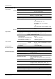
LED Indication Function Remarks, troubleshooting
Green Lit
Control mode Automatic operation; everything o.k.
Flashing
Calibration in pro-
gress
Wait until calibration is finished
(green or red LED will be lit)
Red Lit Calibration error
Internal error
Recalibrate (operate button in opening 1x)
Replace electronics module
Flashing
Mains fault
Check mains network (outside the frequency or
voltage range)
Both Dark
No power supply
Electronics faulty
Check mains network, check wiring
Replace electronics module
Forced control input ZC
Signal priority
Calibration
When is a calibration
required?
Indication of operating
state