
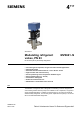
Data Sheet for Product


4 / 20
Siemens Modulating refrigerant valves, PN 63 CE2N4717en
Smart Infrastructure 2019-11-25
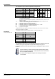
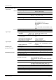
Switch Function ON / OFF Description
1
ON
Positioning signal Y
ON Current [mA]
OFF Voltage [V]
1)
2
ON
Positioning range Y and U
ON DC 2…10 V, 4…20 mA
OFF DC 0…10 V, 0…20 mA
1)
3
ON
Position feedback U
ON Current [mA]
OFF Voltage [V]
1)
4
ON
Nominal flow rate k
vs
ON 63 %
OFF 100 %
1)
1)
Factory setting
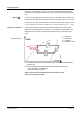
When k
vs
reduction (DIL switch 4 in
position ON) the stroke will be lim-
ited to 63 % mechanical stroke. 63
% of full stroke then corresponds to
an input / output signal of 10 V.
If, in addition, the stroke is limited
to 80 %, for example, the minimum
stroke will be
0.63 x 0.8 = 0.50 of full stroke.
80 %
100 %
4716D01en
0 %
0 %
100 %
Y-input
Stroke
In the case of the suction throttle valve, it is
essential that a minimum stroke limit be
maintained to ensure compressor cooling
and efficient oil return. This can be
achieved with a reinjection valve, a bypass
line across the valve, or a guaranteed
minimum opening of the valve. The mini-
mum stroke can be defined via the control-
ler and control signal Y, or it can be set
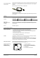
directly with potentiometer Rv.
The factory setting is zero (mechanical stop in counterclockwise direction, CCW). The
minimum stroke can be set by turning the potentiometer clockwise (CW) to a maximum
of 80 % k
vs
.
Under no circumstances must potentiometer Rv be used to limit the stroke on
expansion applications. It must be possible to close the valve fully.
Configuration of
DIL switches
k
vs
-
reduction
Minimum stroke set-
ting
Attention