
Data Sheet for Product


18 / 20
Siemens Modulating refrigerant valves, PN 63 CE2N4717en
Smart Infrastructure 2019-11-25
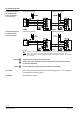
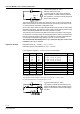
Use of the MVS661..N as a suction throttle valve
70177
+
–
MVS661...N
Bypass
Typical control range 50...100 %.
Minimum stroke limit control:
To ensure optimum cooling of the compressor,
either a capacity controller must be provided for
the compressor, or a minimum stroke must be set
via the valve electronics.
The minimum stroke can be limited to a maximum of 80 %. At zero load, the minimum
stroke must be sufficient to ensure that the minimum gas velocity in the suction line is >
0.7 m/s and that the compressor is adequately cooled.
As the control valve closes, the evaporating temperature rises and the air-cooling effect
decreases continuously. The electronic control system provides demand-based cooling
without unwanted dehumidification and costly retreatment of the air.
The pressure at the compressor inlet falls and the power consumption of the compres-
sor is reduced. The energy savings to be anticipated with low loads can be determined
from the compressor selection chart (power consumption at minimum permissible suc-
tion pressure). Compressor energy savings of up to 40 % can be achieved.
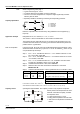
The recommended differential pressure ∆p
V100
across the fully open control valve
is between 0.15 < ∆p
V100
< 0.5 bar.
Refrigerant R134A; Q
0
= 9,5 kW; t
o
= 4 °C; t
c
= 40 °C;
Differential pressure across MVS661..N: Dp
V100
= 0,25 bar
In this application example, t
o
, t
c
and ∆p
V100
are to be interpolated.
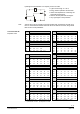
KS R134a t
o
= 0 °C t
o
= 10 °C Interpolation at t
o
= 4 °C
0,15 / 20 2.2 2.7 2,2 + [(2,7 - 2,2) x (4 - 0) / (10 - 0)] 2,4
0,15 / 50 1.7 2.1 1,7 + [(2,1 - 1,7) x (4 - 0) / (10 - 0)] 1,9
0,45 / 20 3.6 4.5 3,6 + [(4,5 - 3,6) x (4 - 0) / (10 - 0)] 4,0
0,45 / 50 2.7 3.4 2,7 + [(3,4 - 2,7) x (4 - 0) / (10 - 0)] 3,0
t
o
= 4 °C t
c
= 20 °C t
c
= 50 °C
Interpolation at t
c
= 40 °C
Dp
v100
0,15
2.4 1.9 2,4 + [(1,9 - 2,4) x (40 - 20) / (50 - 20)] 2,1
Dp
v100
0,45
4.0 3.0 4,0 + [(3,0 - 4,0) x (40 - 20) / (50 - 20)] 3,3
t
c
= 40 °C
Dp
v100
0.15 Dp
v100
0.45
Interpolation at
Dp
v100
0,25
2.1 3.3 2,1 + [(3,3 - 2,1) x (0,25 - 0,15) / (0,45 - 0,15)] 2,5
k
vs
theoretical = 9,5 kW / 2,5 = 3,8 m
3
/h
Valve MVS661.25-6.3N is suitable, since 3.8 m
3
/h / 6.3 m
3
/h x 100 % = 60 % (> 50 %)
It is recommended that the k
vs
value be set to 63 % = 4 m
3
/h
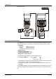
509 41 A
+
–
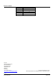
Typical control range 10...100 %.
The capacity controller ensures that the com-
pressor is adequately cooled, making it unnec-
essary to set a minimum stroke in the refriger-
ant valve.
Application example