
Data Sheet for Product


Technical Instructions MVS661..N Series Modulating Refrigerant Valves
Document Number 155-404 for Ammonia (R717) and Safety Refrigerants
May 11, 2016
Page 6 Siemens Industry, Inc.
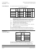
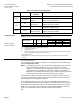
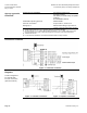
Table 4. Indication of Operating State.
LED
Indication
Operating State,
Function
Remarks, Troubleshooting
Green
Lit
Control mode
Automatic operation; everything is OK.
Flashing
Calibration in
progress
Wait until calibration is finished
(green or red LED will be lit).
Red
Lit
Calibration error
Internal error
Recalibrate (operate button in opening 1×).
Replace electronics module.
Flashing
Main fault
Check electric main network (outside the
frequency or voltage range).
Both
Dark
No power supply
Electronics faulty
Check electric main network, check wiring
Replace electronics module.
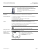
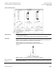
Connection type
4-wire connection
3-wire connection
NOTE: Four-wire connections are always preferred.
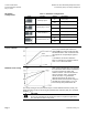
Product Number
(VA)
(W)
(A)
Wire Gauge (AWG)
14
12
10
Max. Cable Length Ft (m)
MVS661..-..
22
12
1.6 to 4A
213 (65)
361 (110)
525 (160)
MVS661..-..
22
12
1.6 to 4A
65 (20)
115 (35)
164 (50)
S
NA
= Nominal apparent power for selecting the transformer.
P
med
= Typical power consumption.
I
F
= Required slow fuse.
L = Maximum cable length; with 4-wire connections, the maximum permissible length of the separate 14 AWG
(1.5 mm
2
) copper positioning signal wire is 656 ft (200 m).
1)
All information at 24 Vac.
2) With 10 AWG (4 mm
2
) electrical wiring reduce wiring cross-section for connection inside valve to 12 AWG
(2.5 mm
2
).
Sizing
For straightforward valve sizing, see Application Examples, beginning on page 12 for
the relevant application.
For accurate valve sizing, Siemens Industry, Inc. recommends using the valve sizing
software Refrigeration VASP.
NOTE: The refrigeration capacity Q
0
is calculated by multiplying the mass flow by the
specific enthalpy differential found in the h, log p-chart for the relevant
refrigerant. To easily determine the refrigeration capacity, see the selection
chart provided for each application. With direct or indirect hot-gas bypass
applications, the enthalpy differential of Q
c
(the condenser capacity) must also
be taken into account when calculating the refrigeration capacity.
If the evaporating and/or condensing temperatures are between the values shown in
the tables, the refrigeration capacity can be determined with reasonable accuracy by
linear interpolation. See Application Examples.
At the operating conditions given in the tables, the permissible differential pressure
p
max
363 psi (25 bar) across the valve is within the admissible range for these valves.
If the evaporating temperature is raised by 1K, the refrigeration capacity increases by
about 3%. If sub-cooling is increased by 1K, the refrigeration capacity increases by
about 1 to 2% (this applies only to sub-cooling down to approximately
8K).